Combined Action of Uniform Flow and Oscillating Flow Around Marine Riser at Low Keulegan-Carpenter Number
DENG Yue, HUANG Weiping,, and ZHAO Jingli
1) Shandong Provincial Key Laboratory of Ocean Engineering, Ocean University of China, Qingdao 266100, P. R. China
2) Marine Technology Center, Shandong Marine Fisheries Research Institute, Yantai 264006, P. R. China
Combined Action of Uniform Flow and Oscillating Flow Around Marine Riser at Low Keulegan-Carpenter Number
DENG Yue1), HUANG Weiping1),*, and ZHAO Jingli2)
1) Shandong Provincial Key Laboratory of Ocean Engineering, Ocean University of China, Qingdao 266100, P. R. China
2) Marine Technology Center, Shandong Marine Fisheries Research Institute, Yantai 264006, P. R. China
With the increase of petroleum and gas production in deep ocean, marine risers of circular cylinder shape are widely used in the offshore oil and gas platform. In order to research the hydrodynamic performance of marine risers, the dynamic mesh technique and User-Defined Function (UDF) are used to simulate the circular cylinder motion. The motion of a transversely oscillating circular cylinder in combination of uniform flow and oscillating flow is simulated. The uniform flow and oscillating flow both are in x direction. SIMPLE algorithm is used to solve the Navier-Stokes equations. The User-Defined Function is used to control the cylinder transverse vibration and the inlet flow. The lift and drag coefficient changing with time and the map of vorticity isolines at different phase angle are obtained. Force time histories are shown for uniform flow at Reynolds number (Re) of 200 and for the combination of uniform and oscillating flows. With the increase of amplitude of oscillating flow in combined flow, the change of lift amplitude is not sensitive to the the change of cylinder oscillating frequency. Lift amplitude increases with the increase of oscillating flow amplitude in the combined flow, but there is no definite periodicity of the lift coefficient. The drag and inertia force coefficients change when the maximum velocity of the oscillating flow increases in the combined flow. The vortex shedding near the circular cylinder shows different characteristics.
transversely oscillating cylinder; circular cylinder; marine riser; uniform flow; oscillating flow; vorticity isolines
1 Introduction
tex is switching. Wang and Zhou (2005) studied a circular cylinder oscillating transversely in still water and in a uniform flow, and verified the conclusion of Lu and Dalton (1996) and Dutschet al.(1998). Meneghini and Bearman (1995) obtained the boundary of lock-in for small amplitudes of oscillations. The ratiof/fsvaried from 0.7 to 1.15 and forA/Dfrom 0.025 to 0.6 in the simulation. Williamson and Roshko (1988) carried out experiments for large amplitudes of oscillation. Anagnostopoulos and Bearaman (1992) conducted experiments on the vortex-induced transverse oscillations of a circular cylinder at low Reynolds number ranging between 90 and 150. The amplitude of the lift force in phase with the circular cylinder velocity was maximum at the lower limit of the lock-in region. Zhao and Chen (2006) reproduced these results by Lagrangian-Eulerian (ALE) method and verified the conclusion of Mendes and Branco (1999). Wan and Turek (2007) investigated the numerical simulation of particulate flows using a new moving mesh method combined with the multigrid fictitious boundary method (FBM) for the implicit treatment of Dirichlet boundary conditions with applications to incompressible flow simulations. Liang and Wan (2009a, b) studied the forced oscillation and vortex-induced motion of circular cylinder in cross flow with low Reynolds number. Singha and Sinhamahapatra (2010) did research about the flow past a
In recent years, increasingly more and more oil and natural gas exploration and production have shifted to deeper ocean. Marine riser design and constraction remain to be technically challenging in deep sea. More and more pivotal components of circular cylinder shape represented by marine risers are widely used in the offshore oil platform and subsea pipeline systems. Many work focus on the research of circular cylinder in uniform flow and oscillating flow. Many excellent experiments and numerical simulations have been done in the fields of flow around circular cylinder. Guet al.(1994) found that vortexes from one side of the cylinder to the other reach a high degree of concentration of vorticity next to cylinder when the ratiof/fsincreases (fis the oscillating frequency of cylinder,fsis the shedding frequency for the fixed cylinder ). Lu and Dalton (1996) studied the vortex shedding from a transversely oscillating circular cylinder in a uniform flow by numerical solutions. The impact of increasing the amplitude of oscillating cylinder and Reynolds number are shown to lower the value off/fsat which vor-circular cylinder between parallel walls at low Reynolds number. Zhaoet al.(2010) investigated combined steady and oscillatory flow past a circular cylinder by three-dimensional direct numerical simulation. The incompressible Navier-Stokes equations are solved by finite element method. Carmoet al.(2011) performed numerical simulations of the flow around two circular cylinders in tandem arrangements. The Reynolds number was kept constant at 150 for two-dimensional simulations and at 300 for three-dimensional simulations. They found that for the tandem arrangements cylinder lock-in boundaries are wider than those for the isolated cylinder and the maximum displacement amplitudes are greater. Raghavan and Bernitsas (2011) found that Reynolds number has significant effects on the response of an elasticity- mounted cylinder in flow; but they did not consider the combination of uniform and oscillating flow. Fanet al.(2012) simulated the 2D and 3D viscous flow around circular at high Reynolds number and found that the 3D lift coefficient are smaller than the 2D results. Donget al.(2012) investigated the two dimensional flow around a cylinder using Discrete Vortex Method and obtained the wake shapes, lift coefficients and response amplitudes of different mass ratios and reduced velocities.
There are few papers and research work on combination of uniform flow and oscillating flow so far. But the case of combined flow simulation is more practical. This paper deals with transversely oscillating circular cylinder in the combined uniform flow and oscillating flow at low Reynolds number by the dynamic mesh technique and User-Defined Function (UDF). The uniform flow and oscillating flow both are in thexdirection. Lift coefficient and drag coefficient changing with time have been simulated. The case of fixed cylinder in uniform flow have been simulated to test and verify the model and Strouhal number (fsD/U).
2 Numerical Computations
Control equations are the two-dimensional incompressible viscous flow Navier-Stokes equations, the continuity equation and momentum equation in cartesian coordinates being
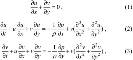
whereuis the velocity inxdirection,vthe velocity inydirection,pthe pressure,ρthe density of fluid, andvthe kinematic viscosity coefficient. In this paper,ρ=998.2 kg m-3.
The key coefficients involved depend on both the Reynolds number Re and the Keulegan-Carpenter numberKC, which are defined as
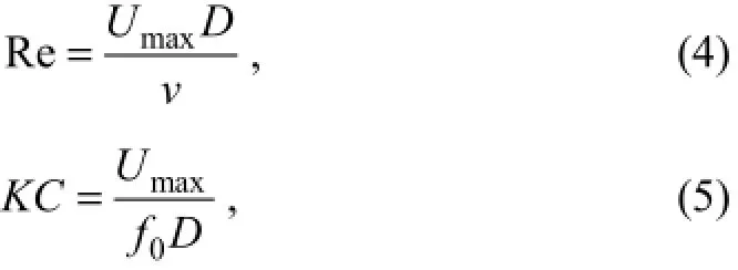
whereUmaxis the maximum velocity of the oscillating flow,vis the kinematic fluid viscosity,f0is an oscillating flow frequency andDis the diameter of the cylinder.
The oscillating flow and the oscillating flow velocity in the numerical simulation are sinusoid and cosinusoid, respectively,

whereBis the amplitude of the oscillating flow with the velocityU1.
Thus the Keulegan-Carpenter number can be written as

The transverse oscillation of the circular cylinder considered in the numerical simulations is also sinusoidal

whereAdenotes the amplitude of the cylinder motion andfis the oscillating frequency.
The force components are solved inxandydirections with drag force inxdirection and lift force inydirection. Drag and lift forces are then nondimensionalized as follows:
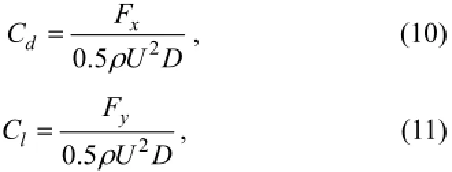
whereCdis the drag coefficient,Clis the lift coefficient,Uis the average velocity of flow,FxandFyare forces inxandydirections, respectively.
An overall view of the calculation region is shown in Fig.1. The diameter of the cylinderDis 0.02 m. The outflow length is 80Dand the width of the domain is 20D. The cylinder is at the center with side boundaries located at 10D. The 10D×10Drange around the circular cylinder is the dynamic mesh, which will move with the cylinder along the interfaces. Fluent13 software is used in the numerical simulation.

Fig.1 Computational domain for the transversely oscillating cylinder.
3 Results and Discussion
3.1 Uniform Flow Around a Fixed Cylinder
In order to obtain a better mesh to perform numerical simulations of a circular cylinder in a combination of uniform and oscillatory flows at low Reynolds number, three different computational meshes have been obtained for evaluating the Strouhal number (fsD/U).
#cvperimeteris the number of control volumes on the cylinder perimeter and #cvtotalis the total number of control volumes employed. Three different meshes are shown in Table 1.

Table 1 Grids parameters of the three computational meshes
As the obtained Strouhal number in Table 2, the results of mesh2 and mesh3 have a good agreement with the reference values obtained by Brazaet al.(1986) and Meneghini and Bearman (1995). In order to save computational time, Mesh2 is selected to perform the numerical simulations presented below (Fig.2).

Table 2 Strouhal number of uniform flow around the fixed cylinder at Re=200

Fig.2 Grids center of the computational mesh around the circular cylinder of Mesh2.
3.2 Combined Uniform and Oscillating Flow Around a Transversely Oscillating Cylinder
Ocean environment is very complex. Both uniform flow and oscillatory flow can be found in deep water. It’s of great practical significance to carry out the research on motion of a circular cylinder in a combination of uniform and oscillatory flow.
The simulations are carried out for values off/fs, wherefis the frequency of oscillating cylinder andfsis the shedding frequency for the fixed cylinder in uniform flow at Re=200,f/fs=0.85, 1.0, 1.15 and for nondimensional numberA/D=0.2. The frequency of oscillating flowfis 0.0989 (same asfs). Simulations were carried out keepingA/Dconstant and run with different values off/fsand Re. The uniform flow and oscillating flow both are inxdirection.
3.2.1 Transversely oscillating circular cylinder in uniform flow
Lift and drag coefficients (Cl,Cd) for the case of a transversely oscillating cylinder at a Reynolds number equal to 200 in uniform flow are shown in Fig.3. It can be found that the time histories of lift and drag coefficient are periodically changing and the amplitude of oscillation remains constant whenf/fs=0.85, 1.0. But, the amplitudes ofClandCddepict a beating phenomenon whenf/fs=1.15. In Fig.3, the amplitudes ofClandCdincrease with the increase of cylinder oscillating frequency. These are the same as in the conclusion of Wang and Zhou (2005).
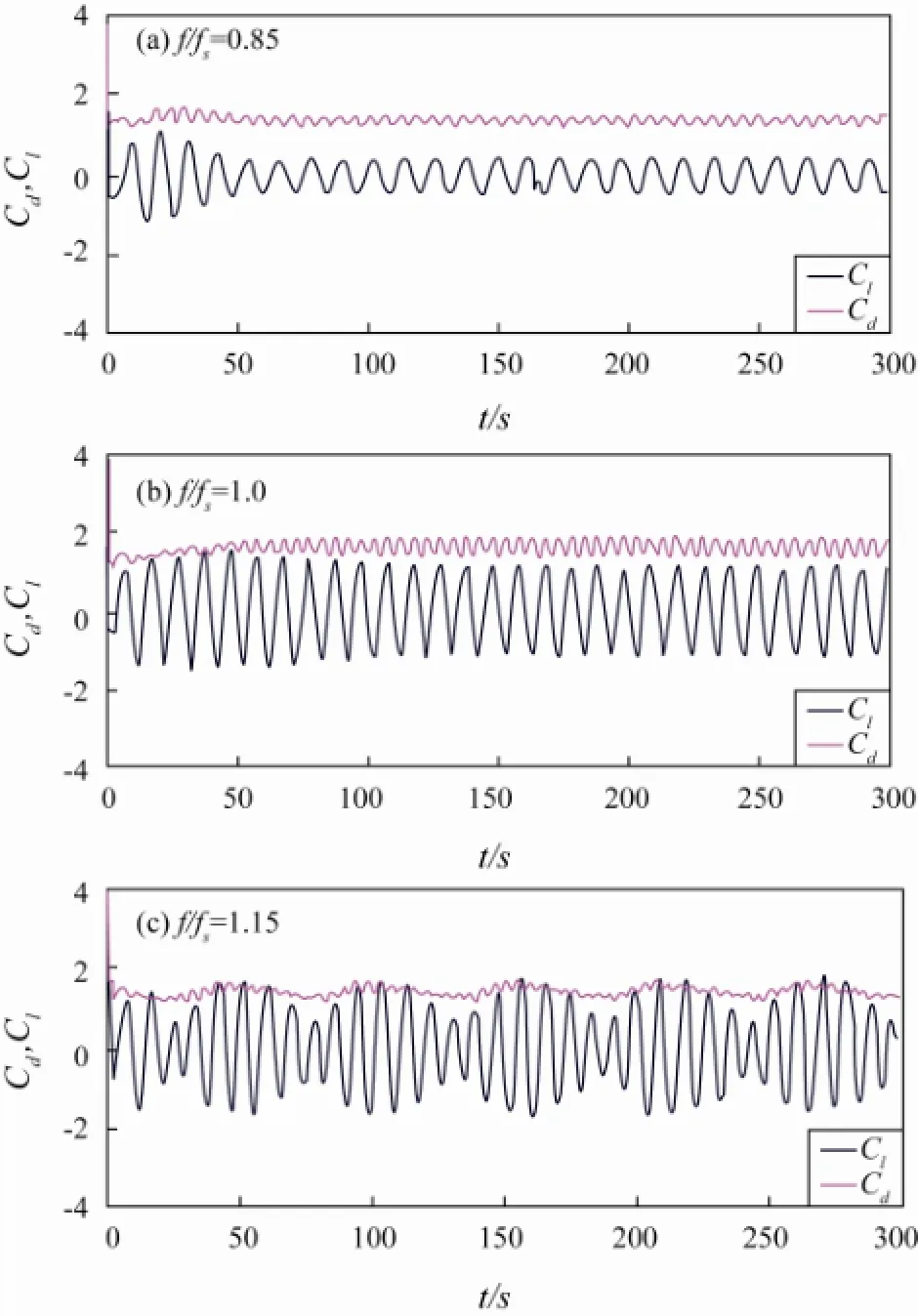
Fig.3 Drag and lift coefficient time histories of transversely oscillating cylinder in uniform flow, Re=200,A/D=0.2.
3.2.2 Transversely Oscillating Circular Cylinder in a Combination of Uniform Flow and Oscillating Flow
In Fig.4 and Table 3, the case of transversely oscillat-ing cylinder in a combination of uniform flow and oscillatory flow is shown, for uniform flow Re=200 and for oscillating flow Re=15,KC=0.38; the parameters Re andKCof the oscillating flow are very small. The change of lift coefficient (Cl) is not obvious; it behaves similarly to those shown in Fig.3. The amplitudes of lift also increase with the increase of cylinder oscillating frequency. In Table 3, the drag coefficients (Cd) and inertia force coefficients (Cm) increase with the increase of frequency ratio in lock-in region (f/fs=0.85,f/fs=1.0), but decrease when the frequency ratio increases to 1.15, which is outside the lock-in region.
In Fig.5, for the case with a cylinder in combined flow (uniform flow Re=200 and oscillating flow Re=100,KC=2.51). The amplitude of lift coefficient (Cl) is larger than for a uniform flow (in Fig.3) and for a combination of uniform flow and oscillatory flow with small Re andKC(Fig.4). Amplitudes of lift have no obvious increase with the increase of cylinder oscillating frequency. These phenomena have not been found for the cases in Figs.3 and 4. Comparing Fig.5 with Figs.3 and 4, the periodicity of the lift coefficient only can be found in one case (Fig.5b). There is no obvious periodicity inf/fs=0.85, 1.15 (Figs.5a, c). From Table 4, it can be seen easily that the value of drag coefficients (Cd) and inertia force coefficients (Cm) are very close in the three frequency ratios. TheCdandCmof the frequency ratio equal to 1.0 are larger than the others. Comparing Table 3 with Table 4, the value ofCdandCmdecrease when the maximum velocity of the oscillating flow (Umax) increases in a combined flow.
In order to more clearly show the results of the above, a summary is listed in Table 5.
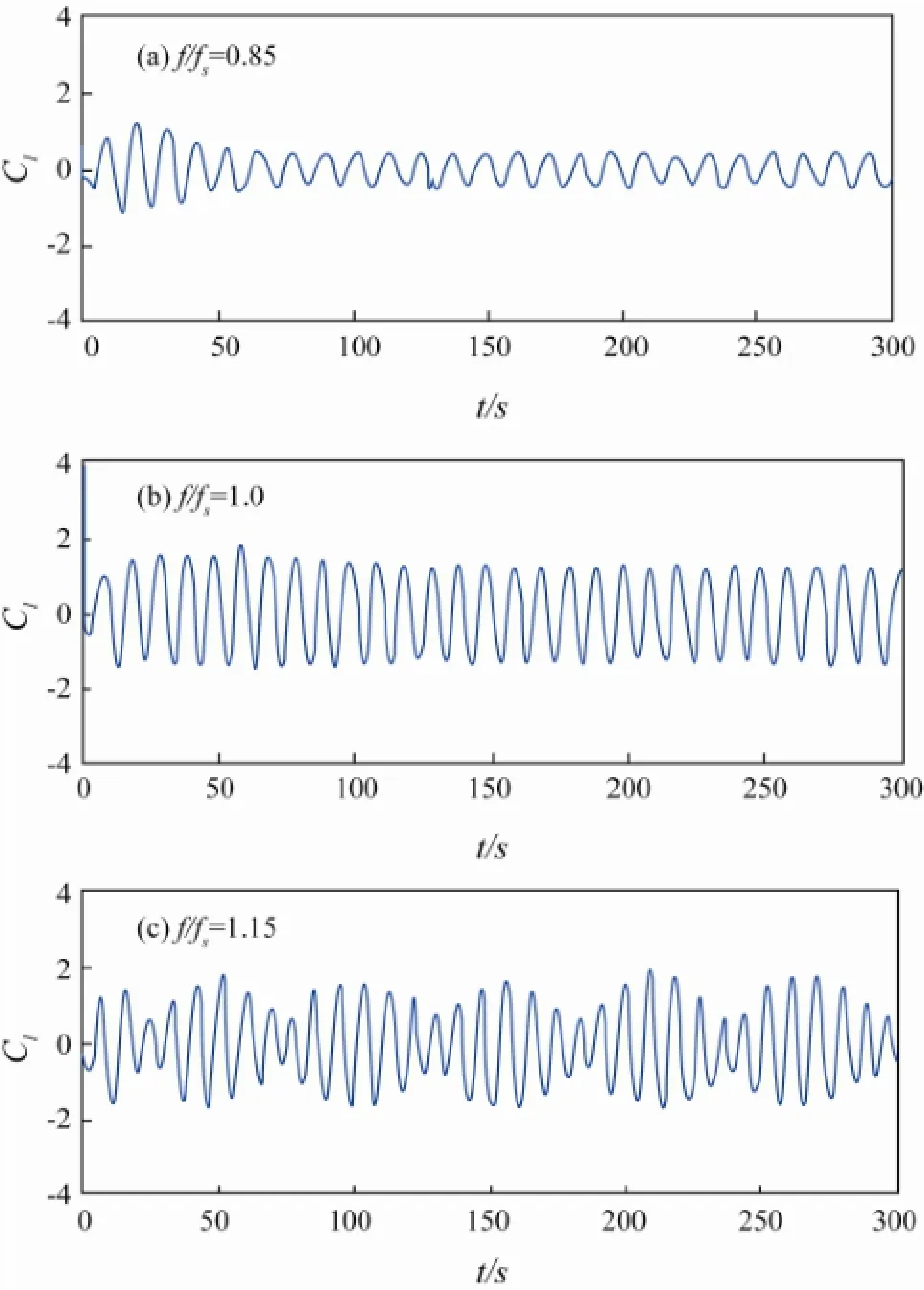
Fig.4 Lift coefficient time histories of transversely oscillating cylinder in a combination of uniform flow and oscillating flow, A/D=0.2. For uniform flow Re=200; for oscillating flow Re=15, KC=0.38.
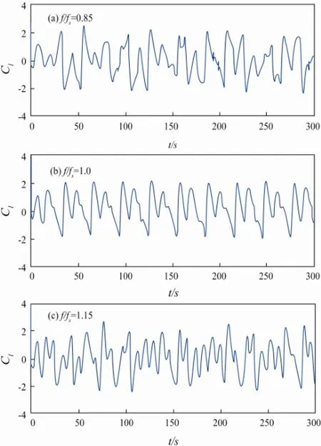
Fig.5 Lift coefficient time histories of transversely oscillating cylinder in a combination of uniform flow and oscillating flow, A/D=0.2. For uniform flow Re=200; for oscillating flow Re=100, KC=2.51.

Table 3 Cdand Cmof transversely oscillating cylinder in a combination of uniform flow and oscillatory flow, A/D=0.2. For uniform flow Re=200, for oscillating flow Re=15, KC=0.38

Table 4 Cdand Cmof transversely oscillating cylinder in a combination of uniform flow and oscillatory flow, A/D=0.2. For uniform flow Re=200; for oscillating flow Re=100, KC=2.51
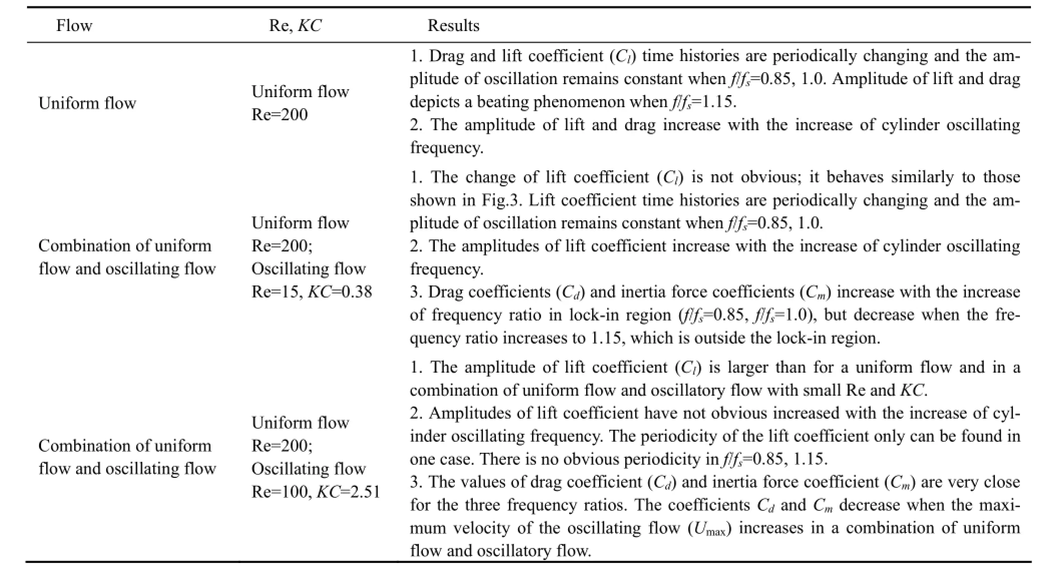
Table 5 Summary for transversely oscillating cylinder in uniform flow and for a combination of uniform flow and oscillatory flow, A/D=0.2
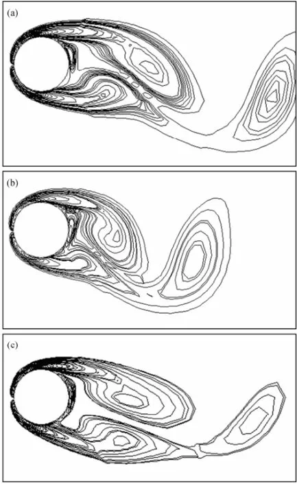
Fig.6 Vorticity isolines at uniform flow for Re=200, A/D=0.2, and phase angle φ=3π/2. (a) f/fs=0.85; (b) f/fs=1.0; (c) f/fs=1.15.

Fig.7 Vorticity isolines in a combination of uniform flow and oscillating flow, phase angle φ=3π/2. (a) Re=200, A/D=0.2, f/fs=1.0; (b) Uniform flow, Re=200, f/fs=1.0. Oscillating flow Re=15, KC=0.38; (c) Uniform flow Re=200, f/fs=1.0. Oscillating flow, Re=100, KC=2.51.
In Fig.6, vorticity isolines for transversely oscillating cylinder in uniform flow are shown with Re=200,A/D= 0.2, and phase angleφ=3π/2,f/fsvarying from 0.85 to 1.15. We can see that the length of upper vortex near the cylinder decreases whenf/fsvaries from 0.85 to 1.0, butthe upper vortex still plays a dominant role. However, the length of upper vortex is equal to that of lower vortex whenf/fs=1.15, and the lower vortex plays the same dominant role as with the upper vortex. If we increase the ratiof/fsto 1.2, the lower vortex will play a dominant role. So vortex switching occurs. These results also prove the conclusion of Wang and Zhou (2005) and Lu and Dalton (1996).
Fig.7a is for a transversely oscillating cylinder in uniform flow with Re=200,A/D=0.2 andf/fs=1.0. Fig.7b is for a transversely oscillating cylinder subjected to a combination of uniform and oscillatory flow. For the uniform flow, Reynolds number is Re=200, whereas for the oscillating flow, Re=15,KC=0.38,A/D=0.2 andf/fs=1.0. Fig.7c is also for the case with a transversely oscillating cylinder in a combination of uniform and oscillatory flow. Differences between Fig.7b and Fig.7c is due to the oscillating flow parameters: Re=100,KC=2.51. We can see that the diameter of upper and lower vortices near the cylinder decreases when the amplitude of oscillating flow increases. In numerical simulation, the uniform flow Re is consistently higher than that of the oscillating flow Re.
In Fig.8, the vortex shedding is 2S mode (Williamson and Roshko, 1988). But the vortex shedding hardly belong to one known mode (2S, 2P, P+S,etc.) in Fig.9. In the simulation, the Reynolds number of the uniform flow is always larger than that of the dynamic oscillating flow.

Fig.8 Vorticity isolines at uniform flow with Re=200, A/D=0.2 and f/fs=1.0.

Fig.9 Vorticity isolines in a combination of uniform flow and oscillating flow with A/D=0.2, f/fs=1.0. For uniform flow, Re=200; for oscillating flow Re=100, KC=2.51.
4 Conclusions
1) The amplitudes of lift coefficient increase with the increase of cylinder oscillating frequency in uniform flow (Re=200) and combined flow (oscillating flow, Re=15,KC=0.38). But the amplitudes of lift coefficient have no obvious raise with the increase of cylinder oscillating frequency in combined flow (oscillating flow, Re=100,KC=2.51). The amplitudes of lift coefficient increase with the increase of oscillating flow amplitude in combined flow, but there is no definite periodicity. Obvious periodicity of lift coefficient can only be observed forf/fs=1.0 (Fig.5b), but not forf/fs=0.85 and 1.15 (Figs.5a, c).
2) Drag coefficient and inertia force coefficient increase with the increase of frequency ratio in lock-in region (f/fs=0.85,f/fs=1.0), but decrease when the frequency ratio increase to 1.15, which is out of the lock-in region. Furthermore, the values of drag coefficient and inertia force coefficient decrease when the maximum velocity of the oscillating flow (Umax) increase in combined flow.
3) The lengths of upper and lower vortices near the cylinder decrease when the amplitude of the oscillating flow increases in combined flow. The vortex shedding also show a special mode. The Reynolds number of the uniform flow is always larger than that of the dynamic oscillating flow in this paper.
Acknowledgements
The authors would like to thank Professor Shan Huang and Professor Atilla Incecik at the University of Strathclyde in UK. They offered much help and guidance when the authors studied there. This study was supported financially by the Natural Science Foundation of China (No. 51079136/51179179/51239008).
Anagnostopoulos, P., and Bearaman, P. W., 1992. Response characteristics of a vortex-excited cylinder at low Reynolds number. Journal of Fluids and Structures, 7: 39-50.
Braza, M., Chassaing, P., and Haminh, H., 1986. Numerical study and physical analysis of the pressure and velocity fields in the near wake of a circular cylinder. Journal of Fluid Mechanics, 165: 79-130.
Carmo, B. S., Sherwin, S. J., Bearman, P. W., and Willden, R. H. J., 2011. Flow-induced vibration of a circular cylinder subjected to wake interference at low Reynolds number. Journal of Fluids and Structures, 27 (4): 503-522, DOI: 10.1016/j. jfluidstructs.2011.04.003.
Dong, J., Zong, Z., Li, Z. R., Sun, L., and Chen, W., 2012. Numerical simulation of flow around a cylinder of two degrees of freedom motion using the discrete vortex method. Journal of Ship Mechanics, 16 (1-2): 9-20.
Dutsch, H., Durst, F., Becker, S., and Lienhart, H., 1998. Low-Reynolds-number flow around an oscillating circular cylinder at low Keulegan-Carpenter numbers. Journal of Fluid Mechanics, 360: 249-271.
Fan, J. J., Tang, Y. G., Zhang, R. Y., and Shao, W. D., 2012. Numerical simulation of viscous flow around circular cylinder at high Reynolds numbers and forced oscillating at large ratio of amplitude. Chinese Journal of Hydrodynamics, 27 (1): 24-32, DOI: 10.3969/j.issn1000-4874.2012.01.004.
Gu, W., Chyu, C., and Rockwell, D., 1994. Timing of vortex formation from an oscillating. Physics of Fluids, 6: 3677-3682, DOI: 10.1063/1.868424.
Liang, L. W., and Wan, D. C., 2009a. Numerical analysis of vortex induced motion of a 2D circular cylinder in cross-flow with low Reynold numbers. Sciencepaper Online, 2: 1754-1764.
Liang, L. W., and Wan, D. C., 2009b. Numerical investigation of a forced oscillating cylinder in a cross flows with low Reynolds number. The Ocean Engineering, 27 (4): 45-53.
Lu, X. Y., and Dalton, C., 1996. Calculation of the timing of vortex formation from an oscillating cylinder. Journal of Fluids and Structures, 10: 527-541.
Mendes, P. A., and Branco, F. A., 1999. Analysis of fluid-
structure interaction by an Arbitrary Lagrangian-Eulerian finite element formulation. International Journal for Numerical Methods in Fluids, 30: 897-919.
Meneghini, J. R., and Bearman, P. W., 1995. Numerical simulation of high amplitude oscillatory flow about a circular cylinder. Journal of Fluids and Structures, 9: 435-455.
Raghavan, K., and Bernitsas, M. M., 2011. Experimental investigation of Reynolds number effect on vortex induced vibration of rigid circular cylinder on elastic supports. Ocean Engineering, 38 (5): 719-731, DOI: 10.1016/j.oceaneng.2010.09. 003.
Singha, S., and Sinhamahapatra, K. P., 2010. Flow past a circular cylinder between parallel walls at low Reynolds numbers. Ocean Engineering, 37 (8): 757-769, DOI: 10.1016/j.oceaneng. 2010.02.012.
Wan, D. C., and Turek, S., 2007. Fictitious boundary and moving mesh methods for the numerical simulation of rigid particulate flows. Journal of Computational Physics, 222 (1): 28-56, DOI:10.1016/j.jcp.2006.06.002.
Wang, Z. D., and Zhou, L. H., 2005. Numerical simulation of circular cylinder oscillating transversely in a uniform stream. Journal of Hydrodynamics, 20: 146-151.
Williamson, C. H. K., and Roshko, A., 1988. Vortex formation in the wake of an oscillating cylinder. Journal of Fluids and Structures, 2: 355-381.
Zhao, L., and Chen, B., 2006. Two-dimensional FEM model of vortex-induced vibration of a circular cylinder. Ocean Technology, 25: 117-121.
Zhao, M., Cheng, L., and An, H. W., 2010. Three-dimensional numerical simulation of flow around a circular cylinder under combined steady and oscillatory flow. Journal of Hydrodynamics, 22 (5): 144-149, DOI: 10.1016/S1001-6058(09)60184-0.
(Edited by Xie Jun)
(Received December 31, 2012; revised February 1, 2013; accepted April 15, 2013)
? Ocean University of China, Science Press and Springer-Verlag Berlin Heidelberg 2014
* Corresponding author. Tel: 0086-532-66781850
E-mail: wphuang@ouc.edu.cn
 Journal of Ocean University of China2014年3期
- Journal of Ocean University of China的其它文章
- Dynamic Response Analysis of a Floating Mooring System
- Effects of Sulfate Chitosan Derivatives on Nonalcoholic Fatty Liver Disease
- Modal Strain Energy Based Structural Damage Localization for Offshore Platform using Simulated and Measured Data
- Laboratory Application of Laser Grain-Size Analyzer in Determining Suspended Sediment Concentration
- Fully Coupled Time-Domain Simulation of Dynamic Positioning Semi-Submersible Platform Using Dynamic Surface Control
- Mean Sea Level Changes near Weizhou Island from 1969 to 2010
