Fully Coupled Time-Domain Simulation of Dynamic Positioning Semi-Submersible Platform Using Dynamic Surface Control
LIANG Haizhi, LI Luyu, and OU Jinping
1) Department of Engineering Mechanics, Dalian University of Technology, Dalian 116024, P. R. China
2) Faculty of Infrastructure Engineering, Dalian University of Technology, Dalian 116024, P. R. China
Fully Coupled Time-Domain Simulation of Dynamic Positioning Semi-Submersible Platform Using Dynamic Surface Control
LIANG Haizhi1),*, LI Luyu2), and OU Jinping2)
1) Department of Engineering Mechanics, Dalian University of Technology, Dalian 116024, P. R. China
2) Faculty of Infrastructure Engineering, Dalian University of Technology, Dalian 116024, P. R. China
A fully coupled 6-degree-of-freedom nonlinear dynamic model is presented to analyze the dynamic response of a semisubmersible platform which is equipped with the dynamic positioning (DP) system. In the control force design, a dynamic model of reference linear drift frequency in the horizontal plane is introduced. The dynamic surface control (DSC) is used to design a control strategy for the DP. Compared with the traditional back-stepping methods, the dynamic surface control combined with radial basis function (RBF) neural networks (NNs) can avoid differentiating intermediate variables repeatedly in every design step due to the introduction of a first order filter. Low frequency motions obtained from total motions by a low pass filter are chosen to be the inputs for the RBF NNs which are used to approximate the low frequency wave force. Considering the propellers’ wear and tear, the effect of filtering frequencies for the control force is discussed. Based on power consumptions and positioning requirements, the NN centers are determined. Moreover, the RBF NNs used to approximate the total wave force are built to monitor the disturbances. With the DP assistance, the results of fully coupled dynamic response simulations are given to illustrate the effectiveness of the proposed control strategy.
dynamic positioning system; coupled analysis; dynamic surface control; RBF NNs; adaptive control
1 Introduction
With the increased oil exploration and exploitation in deep waters, more and more offshore floating structures, such as semi-submersible platforms and drilling ships, are equipped with dynamic positioning (DP) systems, which are used to keep structures at a specified point or track a predefined path. Single-input and output PID (Proportional-Integral-Derivative) control algorithms with low pass filter were first adopted in the drilling ship DP in the 1960s. With the introduction of state space, more advanced control strategies based on optimal control and Kalman filter were proposed. The modified LQG controller was designed by S?rensenet al. (1996). Tannuriet al. (2006) proposed an adaptive control strategy to correct controller gains for DP online, and also the sliding model control later (Tannuriet al., 2010). In these literatures, the dynamic mathematical models are categorized into two types, the wave frequency model and the low frequency model (Balchenet al., 1976, 1980; S?rensen, 2011). The wave frequency model is considered as a wave shaping filter, and the zero-mean Gaussian white noise is inputted as the disturbance. The low frequency model is a specified system to describe the large amplitude drift motions. In the design process, the Kalman filter is first used to separate the low frequency motion from the total motion. Then, the control algorithm calculates control force and torque only based on the low frequency motion.
In the 1990s, a nonlinear DP controller design was proposed. Fossen and Gr?vlen (1998) applied a backstepping method to design a nonlinear observer with an adaptive wave filter for DP. Skjetneet al.(2004, 2005) proposed a back-stepping control combined with adaptive methods for a model ship. But the back-stepping has the problem of an ‘explosion of terms’. The dynamic surface control (DSC) technique was proposed to simplify the back-stepping method through employing a first order filter which replaces the demands of the repeated differentiations in the design process by Swaroopet al.(1997). RBF NNs combined with robust and adaptive back- stepping control were proposed for the nonlinear uncertain systems by Liet al.(2004). Neural networks based DSC was proposed for a class of nonlinear uncertain systems in a strict-feedback form by Wang and Huang (2005). This method was applied in DP of dredgers by Zhang and Jiang (2010). In these nonlinear control strategies, only thehorizontal plane motions were considered, and the effects of the dynamic responses of heave, roll and pith were not analyzed.
In this paper, the nonlinear dynamic mathematical model of a semi-submersible platform is presented. The radiation damping force acting on platform is expressed in terms of convolution integrals accounting for memory effects. The irregular wave frequency forces in the time domain are calculated based on the amplitudes of regular wave forces in the frequency domain. The second order wave forces are calculated using the quadratic transfer function (QTF). To design a control strategy, a simplified linear low frequency mathematical model is adopted. The states of motion used in the design process are filtered from total motions. Radial basis function (RBF) neural networks are designed to compensate external disturbances. Meanwhile, an observer based on RBF NNs and adaptive laws is designed to estimate environment forces.
This paper is organized as follows: In Section 2, a fully coupled 6-degree-of -freedom dynamic model is built and the formulas of wave forces are given. In Section 3, the control strategy of RBF neural networks based on the DSC control is presented. In Section 4, the simulation results are discussed to illustrate the proposed approach.
2 Modeling of Semi-Submersible Platform
2.1 Coordinate System
The coordinate system of a semi-submersible platform is shown in Fig.1. The frameOeXeYeZeis fixed on the earth surface and theXeYeplane is parallel to the still water surface. The frameOXYZis attached to the platform and the coordinate origin of it is denoted asOand located at the center of gravity G as shown in Fig.2.

Fig.1 Coordinate system of the semi-submersible platform.
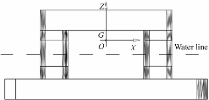
Fig.2 Side view of the semi-submersible platform.
2.2 Hydrodynamics
Fluid is assumed to be ideal and irrotational. Thus, the potential flow theory is adopted to calculate the first order wave excitation force, drift force, radiation damping and added mass that act upon the platform. A hydrodynamic panel element model is shown in Fig.3.
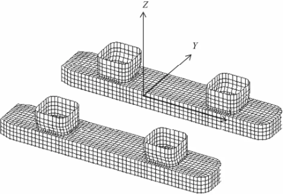
Fig.3 Panel model of semi-submersibe platform.
The flow field in regular harmonic waves is defined by the following velocity potential:

whereφ(X,Y,Z) depends on the spatial components, andωis the wave frequency.
To solve the first order hydrodynamic problem, Dai (1998) assumed: 1) the structure is fixed and wave forces are induced by incident waves that directly acts on the structure; 2) without incident waves, the structure undergoing oscillations diffuses waves outward, which is the cause of radiation wave forces. Based on the assumptions, the total wave potential can be rewritten as

whereIφis the incident wave potential;Dφis the diffraction wave potential;jφis the potential due to thej-thmotion,xj;ωis the frequency of incident waves. The potentials are calculated using the Green’s theorem with required boundary conditions on the surface. When the potentials are known, the fluid force can be calculated by integrating the pressure over the wetted surface:

whereFjis the sum of the fluid force;ρis the water density;njis the generalized surface normal direction;Sis the wetted surface. In reality, waves are irregular and composed of different frequencies. Based on Eq. (3), when the first order wave forces are calculated, irregular waves are considered as a combination of regular waves with different frequencies. Therefore, in the time domain the sum of Froude-Krylov force and diffraction force,both of which are the first order wave forces, are calculated by

whereωjandαjare the frequency and the amplitude of each regular wave component in the spectrum, respec-is the amplitude of the Froude-Krylov and diffraction force corresponding toωj, and it is part of fluid force,Fj;εjis the random phase angle;Nis the number of components.
The quadratic transfer function (QTF) is adopted to calculate the second order wave drift force. Neglecting the summed frequency components, the second order wave force can be written as

2.3 Mathematical Dynamic Modeling
The dynamic equation of motion is given by

For the radiation problem, the memory effects must be considered. The radiation force can be written as

and the equation of motion can be written as

The hysteresis function can be obtained by the inverse Fourier transformation:

whereBkj(ω) is the radiation damping at frequencyω. The added mass-dependent frequency is

whereωcan be any frequency;Akjis the added mass.AkjandBkjcan be obtained from the potentialjφdue to thej-thmotion. Eq. (8) describes the dynamic motion with 6-degree-of-freedom.
3 Control Force Design
The DP is used to counteract environmental forces and keep the platform at a specific location. Considering the propellers’ performance and economic efficiency, only the drift frequency motion in the horizontal plane (surge, sway and yaw) is controlled by the DP. In this section, the DSC is used to design a control strategy for the DP. A drift frequency reference model is needed to design a controller, and the model in a body fixed frame is given by

where the Coriolis term is neglected;ν=[x˙y˙ψ˙]T;x,yandψare the surge, sway and yaw displacement, respectively;Msis the system mass/inertia matrix which includes the system mass/inertia and the drift frequency added mass/inertia,Ms=M+Mα;mis the platform mass;Izis the inertia aboutz-axis; coefficients (Xu˙,Yv˙,Yr˙,Nv˙,Nr˙) inMsare the hydrodynamic parameters;Dis the linear damping matrix of the drift frequency;τEis the environmental force vector;τis the control force vector;the rotation matrix with the properties ofIn the drift frequency dynamic model, the coefficients of added mass/inertia and damping matrixes are assumed to be constants.

The kinematic relationship between the earth-fixed frame and the body-fixed frame is


The control force design process is as follows: Step 1: Consider the displacement error as whereηis the displacement of platform’s horizontal plane degrees of freedom in the global frame;ηdis the predefined point,;λis the path parameter. Because only the station-keeping model is considered in this study, theηdandλare assumed to be zero. Differentiatings1with respect to time, the following equation is obtained,

To trackvasymptotically,s2is defined aswhere


Substitute Eq. (11) into Eq. (16) to obtain

Fig.4 is the schematic diagram of RBF NNs. Given a compact set Ω∈Rn×n, for anyν∈Ω, the RBF NNs are introduced to approximatewhich is written as

with |δ*|≤δm.θ*∈RNis the weight vector,ξ(v)∈RNis the vector of basic function,δ*is the networks reconstruction error, andδmis the error boundary. Assume that the weight vectorθ*satisfies ||θ*||≤θmax, whereθmaxis a known positive constant. A commonly used basic function is the Gaussian function which is described by

wherej?is the center of the basis function;σis the width of the basis function;N'is the number of the centers of the basic function.
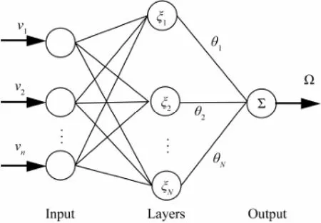
Fig.4 Radial basic function neural networks.
Let


whereμ>0 is a constant parameter.
The differentiation ofvwith respect to time in Eq. (20) is directly obtained from Eq. (15) in the back-stepping method. However, for annth order system, the differentiation needs to be done repeatedly at every time step. The problem of ‘explosion of terms’ will appear in the control force. In order to avoid this problem,vin the DSC is passed through a first order filter with the time constantτ2with

From Eqs. (20), (21) and (22), the control force in horizontal plane is obtained. To analyze the stability of the system, the total Lyapunov function is defined as


Using the adaptive law (Eq. (21)), Eq. (24) is rewritten as

Substitute

into Eq. (25),
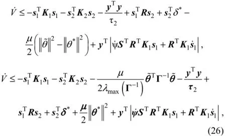
whereλmax(Γ-1) is the maximum eigenvalue ofΓ-1. In theright hand side of inequality (26), there exists

whereλmin(K1) andλmin(K2) are the minimum eigenvalues ofK1andK2, respectively.
BecauseK1,K2andΓ-1are all positive, non-negativeαis defined as

The first four terms in the right hand side of inequality (26) can be written as
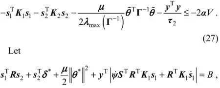
andBis a continuous function bounded by a positive number,B0. Substitute Eq. (27) into Eq. (26), the following inequality is obtained:

For all initial conditions,V≤pcan be chosen, wherepis a positive number. Thus, ifand the control force of the DP will make the system uniformly ultimately bounded.
4 Numerical Simulations
The semi-submersible platform adopted in this study is HYSY-981 (Qiaoet al., 2011). The main structure of HYSY-981 consists of two pontoons, four columns, deck, and derrick. The measures of pontoons, columns, and deck are 114.07 m×20.12 m×8.54 m, 17.385 m×17.385 m ×21.46 m, and 74.42 m×74.42 m×8.60 m, respectively. The top and bottom sizes of derrick are 17 m×17 m×22 m and 17 m×17 m×42 m, respectively. The waterline from the pontoon base is 19 m and the water depth is 1500 m. The weight of platform is 53140 ton.
Fig.5 illustrates the simulation framework. Two parallel systems are constructed: 1) the low frequency control force system; 2) the observer system of wave forces. The low pass filter is introduced to separate low frequency motions from total motions and it is given by


Fig.5 Framework of the control system.
The wind force is compensated through the feed-forward control strategy (S?rnsenet al., 1996) and the current force is generally considered as constant, so in this paper only the wave force is considered and the JONSWAP spectrum is adopted. The significant wave height is 6.0 m, the spectral peak period is 7.9 s, and the peak enhancement factor is 2.0. The wave direction is 45° relative to X-axis of the earth fixed frame. The targeted position is [0, 0] in horizontal plane. In the frequency domain hydrodynamic parameters of added mass, added damping and QTF are calculated by AQWA and the wave forces are calculated in the time domain using MATLAB routines.
To illustrate the control strategy, a time-domain simulation is conducted. The design parameters areK1=diag(0.2, 0.2, 0.2) andK2=diag(0.3, 0.3, 0.3). The first order filter constant of the DSC isτ2=100. In the observer system, the NNs centers ?jof surge and sway velocities are evenly spaced with 101 nodes of the [-10, 10] domain. And the centers ?jof yaw angle velocity are evenly spaced with 101 nodes of the [-1, 1] domain. Corresponding to the centers, all the widths,σ, are 0.5. In the control force design, the centers ?jof the abovementioned velocities are all evenly spaced with 101 nodes of the [-10, 10] domain, and the width,σ, is 0.5 for surge and sway, and 0.05 for yaw. The parameters of the adaptive law areΓ=diag(2)101×101andμ=diag(4)101×101. In the simulations, the Adams-Moulton method is adopted to calculate dynamic motion.
The damping factor of the low pass filter is 2, and the filtering frequency is 0.3 Hz. Using the low pass filter, large amplitudes of low frequency motions are controlled. The time histories of displacement and velocity are shown in Figs.6 and 7. The displacement of horizontal plane satisfies the requirement of less than 3% of water depth. In Fig.6, the larger maximum amplitude of pitch and roll compared to yaw can be attributed to the losing controlfor these degrees of freedom.
The time histories of control forces and wave forces are shown in Figs.8 and 9, respectively. Because the horizontal low frequency motion is controlled, the neural network approximations in control design only contain low frequency components and are smaller than wave forces. Meanwhile, the total wave forces are tracked by the observer system with certain errors. Fig.10 shows the power spectral densities of surge control force, wave forces and observer results in the frequency domain. It can be observed that higher power spectral densities of control force correspond to low frequencies. In the observer system, total horizontal velocities instead of the low frequency velocities are selected as the NNs’ inputs in the control design process. However, the adaptive law is still based on the control force design for convenience in the observer simulations. As a result, the values ofwill make the low frequency components of observer results lager than wave forces. It can be concluded that the observer only assists in monitoring the wave forces.
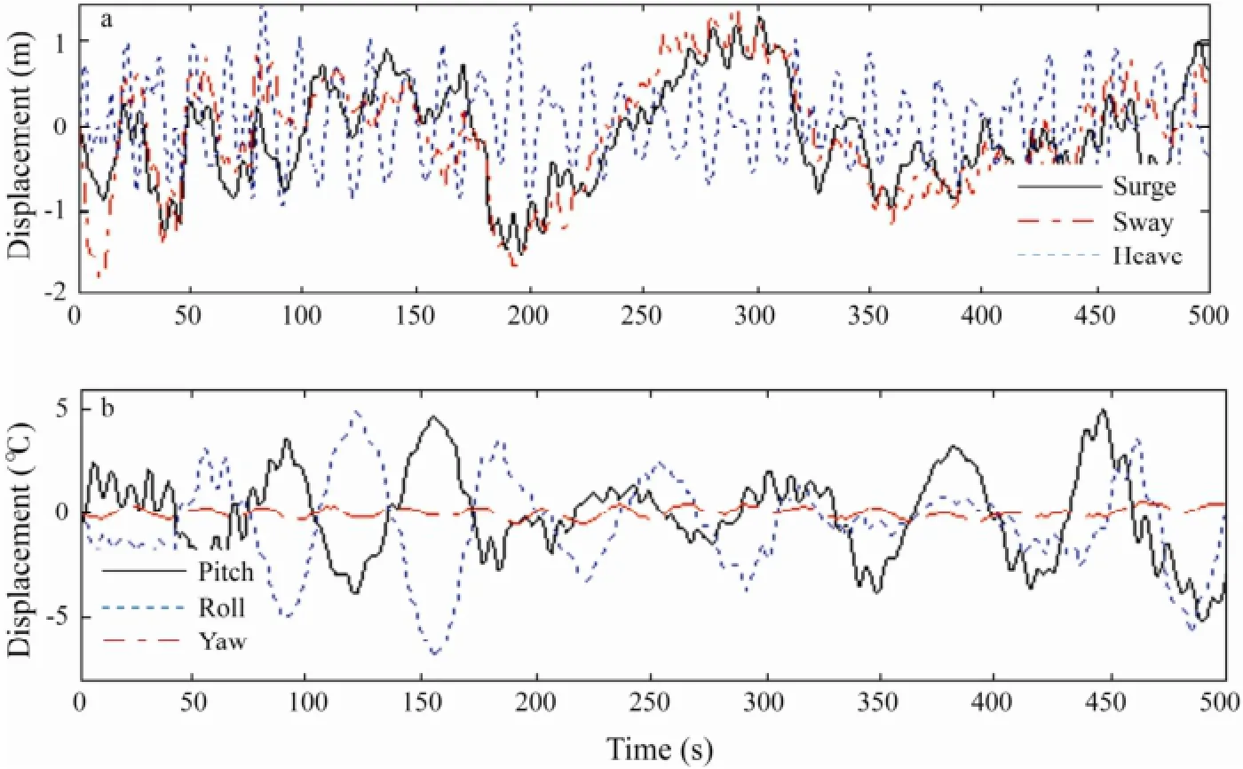
Fig.6 The time history of displacement.
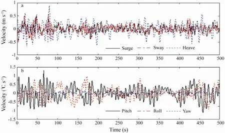
Fig.7 The time history of velocity.

Fig.8 The time history of control force/torque.
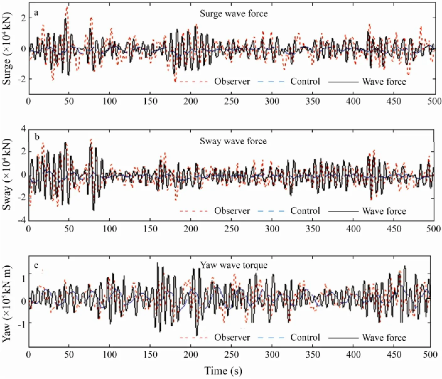
Fig.9 The time history of wave forces for different design modes.
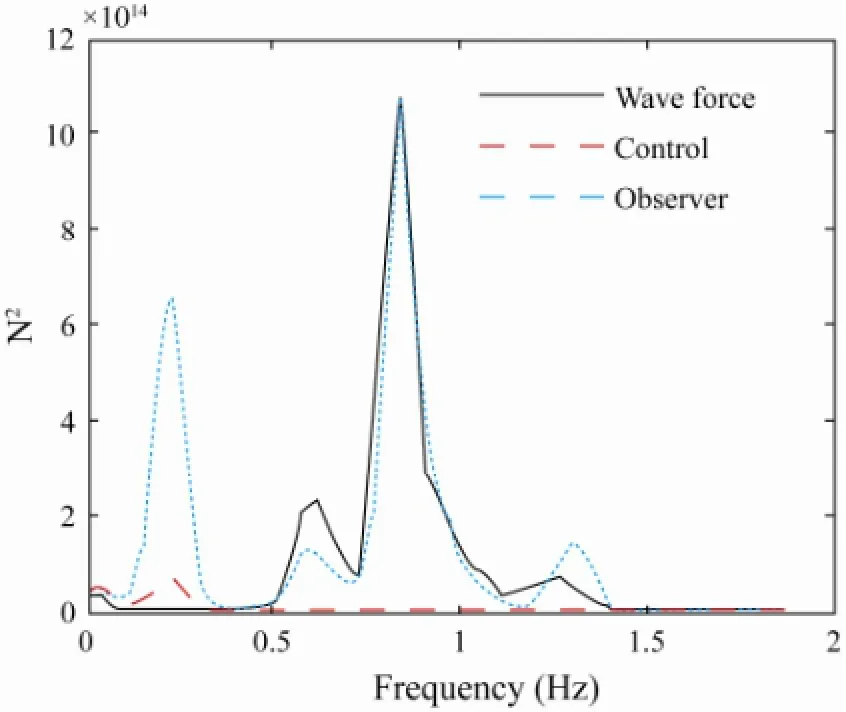
Fig.10 Power spectral density in surge direction.
In order to reduce propellers’ wear and tear, the ideal setup is that the control force is only used to counteract low frequency wave forces. This performance depends on the filtered frequencies. Taking the surge force as an example, the results are given in Fig.11 to illustrate the filtered frequency effects on the control force. It can be seen that the power spectral density gradually increases as the frequency decreases. The reason is that high filtered frequencies decrease filtered velocities. The lower filtered velocities are imported into the NNs, and then wave forces are amplified by Eq. (19). So a proper filtered frequency is needed to balance the propellers’ wear and tear and the power consumption.
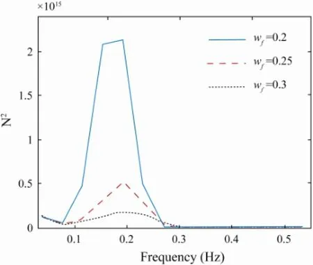
Fig.11 Power spectral density of surge control force.
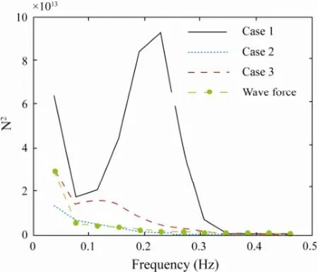
Fig.12 PSD of surge controller compensator in low frequency range.
The choices of NNs centers for the controller compensator are analyzed and the simulated power spectral densities are given in Fig.12. Cases 1, 2, and 3 have 101, 51, and 201 network nodes within [-10, 10], [-10, -0.2] and[-10, -0.2], respectively. Compared with the symmetrical distribution in case 1, the unilateral distribution is more accurate corresponding to wave forces. It can be clearly seen that the larger distribution range results in the higher power for the same number of nodes. For the same distribution range, the more NNs nodes will consume more power. Fig.13 shows that three time series of surge displacement correspond to the counterparts in Fig.12, respectively. The positioning results of case 1 with the larger control force are more accurate than those of the other cases. However, considering the power consumption and positioning requirements, case 2 or 3 is more acceptable. The proper choice of NNs nodes is very important for the control system.
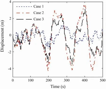
Fig.13 The time history of displacement.
5 Conclusions
This paper presents a control strategy for the semisubmersible platform equipped with a dynamic positioning system. A fully coupled 6-degrees-of-freedom nonlinear dynamic mathematical model was derived. The dynamic surface control was adopted to control low frequency motions in horizontal plane. A low pass filter was introduced to reduce the propellers’ wear and tear with a proper filtered frequency. An extremely small frequency might lead to the loose for the positioning capabilities. Using the low pass filter, only the wave forces of low frequency were approximated by the RBF NNs in control design. The selection of NNs nodes was conducted through the power spectral analysis. Considering positioning requirements and power cost, the unilateral distribution about zero point was more acceptable for the control system. In the observer system total wave forces were also observed by RBF NNs. This observer was serving to monitor wave forces. Utilizing the control force of horizontal plane, the fully coupled dynamics of platform were analyzed. The simulation results show that the horizontal displacement satisfies the positioning requirements.
Acknowledgements
This paper is funded by the National Basic Research Program of China (Grant Nos. 2011CB013702 and 2011 CB013703) and the Science Fund for Creative Research Groups of the National Natural Science Foundation of China (Grant No. 50921001).
Balchen, J. G., Jenseen, N. A., and S?lid, S., 1976. Dynamic positioning using Kalman filtering and optimal control theory. IFAC/IFIP Symposium on Automation in Offshore Oil Field Operation, Amsterdam, 183-186.
Balchen, J. G., Jenseen, N. A., Mathisen, E., and Saelid, S., 1980. A dynamic positioning system based on Kalman filtering and optimal control model. Modeling, Identification and Control, 1 (3): 135-163.
Dai, Y. S., 1998. Potential Flow Theory of Ship Motions in Waves in Frequency and Time Domain. National Defence Industry Press, Beijing, 107-117.
Fossen, T. I., and Gr?vlen, A., 1998. Nonlinear output feedback control of dynamically positioned ships using vectorial observer backstepping. IEEE Transactions on Control systems Technology, 6 (1): 121-128.
Li, Y. H., Qiang, S, Zhuang, X. Y., and Kaynak, O., 2004. Robust and adaptive back-stepping control for nonlinear systems using RBF neural networks. IEEE Transactions on Neural Networks, 15 (3): 693-701.
Qiao, D. S., Zhu, H, Ou, J. P., and Wu, F., 2011. Numerical simulation for truncated model tests of deepwater semisubmersible platform with viscous damper compensated system in mooring lines. Proceedings of the International Offshore and Polar Engineering Conference, ISOPE, Hawaii, USA, 557-564.
Skjetne, R., Fossen, T. I., and Kokotovic P. V., 2005. Adaptive maneuvering, with experiments, for a model ship in a marine control laboratory. Automatica, 41: 289-298.
Skjetne, R., Smogeli, ?. N., and Fossen, T. I., 2004. A nonlinear ship maneuvering model: Identification and adaptive control with experiment for a model ship. Modeling, Identification and Control, 25 (1): 3-27.
S?rensen, A. J., 2011. A survey of dynamic positioning control systems. Annual Reviews in Control, 35: 123-136.
S?rensen, A. J., Sagatun, S. I., and Fossen, T. I., 1996. Design of a dynamic positioning system using model-based control. Control Engineering Practice, 4 (3): 359-368.
Swaroop, D., Gerdes, J. C., Yip, P. P., and Herdrick, J. K., 1997. Dynamic surface control of nonlinear systems. Proceedings of the American Control Conference, 3028-3034.
Tannuri, E. A., Agostinho, A. C., Morishita, H. M., and Moratelli Jr., L., 2010. Dynamic positioning systems: An experimental analysis of sliding model control. Control Engineering Practice, 18 (10): 1121-1132.
Tannuri, E. A., Kubota, L. K., and Pesce, C. P., 2006. Adaptive control strategy for the dynamic positioning of a shuttle tanker during offloading operations. Journal of Offshore Mechanics and Arctic Engineering, 128: 203-210.
Wang, D., and Huang, J., 2005. Neural networks-based adaptive dynamic surface control for a class of uncertain nonlinear systems in strict-feedback form. IEEE Transactions on Neural Networks, 16 (1): 195-202.
Zhang, Y. H., and Jiang, J. G., 2010. A novel disturbances compensating dynamic positioning of dredgers based on adaptive dynamic surface control. Transactions on Systems and Control, 5 (5): 323-332.
(Edited by Xie Jun)
(Received June 5, 2012; revised August 8, 2012; accepted March 3, 2014)
? Ocean University of China, Science Press and Springer-Verlag Berlin Heidelberg 2014
* Corresponding author. Tel: 0086-411-84706742
E-mail: hzliang@mail.dlut.edu.cn
 Journal of Ocean University of China2014年3期
- Journal of Ocean University of China的其它文章
- Dynamic Response Analysis of a Floating Mooring System
- Effects of Sulfate Chitosan Derivatives on Nonalcoholic Fatty Liver Disease
- Combined Action of Uniform Flow and Oscillating Flow Around Marine Riser at Low Keulegan-Carpenter Number
- Laboratory Application of Laser Grain-Size Analyzer in Determining Suspended Sediment Concentration
- Modal Strain Energy Based Structural Damage Localization for Offshore Platform using Simulated and Measured Data
- Mean Sea Level Changes near Weizhou Island from 1969 to 2010
