Modal Strain Energy Based Structural Damage Localization for Offshore Platform using Simulated and Measured Data
WANG Shuqing, LIU Fushun, and ZHANG Min
College of Engineering, Ocean University of China, Qingdao 266100, P. R. China
Modal Strain Energy Based Structural Damage Localization for Offshore Platform using Simulated and Measured Data
WANG Shuqing*, LIU Fushun, and ZHANG Min
College of Engineering, Ocean University of China, Qingdao 266100, P. R. China
Modal strain energy based methods for damage detection have received much attention. However, most of published articles use numerical methods and some studies conduct modal tests with simple 1D or 2D structures to verify the damage detection algorithms. Only a few studies utilize modal testing data from 3D frame structures. Few studies conduct performance comparisons between two different modal strain energy based methods. The objective of this paper is to investigate and compare the effectiveness of a traditional modal strain energy method (Stubbs index) and a recently developed modal strain energy decomposition (MSED) method for damage localization, for such a purpose both simulated and measured data from an offshore platform model being used. Particularly, the mode shapes used in the damage localization are identified and synthesized from only two measurements of one damage scenario because of the limited number of sensors. The two methods were first briefly reviewed. Next, using a 3D offshore platform model, the damage detection algorithms were implemented with different levels of damage severities for both single damage and multiple damage cases. Finally, a physical model of an offshore steel platform was constructed for modal testing and for validating the applicability. Results indicate that the MSED method outperforms the Stubbs index method for structural damage detection.
offshore platform; damage localization; strain energy; mode shapes; modal testing
1 Introduction
Offshore platforms, operated in harsh environment and under various external forces, constantly accumulate damage during the span of their service life. Clearly the development of robust techniques for early damage detection and localization is crucial to avoid the possible occurrence of a catastrophic structural failure. Structural damage detection based on vibration measurements holds promise for the global nondestructive damage detection of structures. The essential idea behind this type of methods is that damage would alter the stiffness, damping or mass of the structure, and so change the modal parameters such as modal frequencies and mode shapes. That is to say, changes of modal parameters can be used as a damage indicator. Researchers have provided various damage detection techniques based on modal parameters (Doeblinget al., 1998). But most of them have certain limitations in practice. For example, some methods need mass normalized mode shapes or spatially-complete mode shapes (including structural rotational degrees of freedom); some methods need measured input forces.
Among the damage identification methods based on mode shapes, those related to modal strain energy seem to be promising for locating damages (Seyedpoor, 2012; Wanget al., 2010; Wang and Li, 2012; Yanet al., 2010, 2012). One algorithm, the Stubbs damage index algorithm, is based on decrease in modal strain energy and defined by the curvature of the measured mode shapes (Stubbset al., 1995; Kim and Stubbs, 2002). This algorithm requires the known pre- and post-damage mode shapes, but a few required modes do not need to be mass-normalized. It has been successfully applied to the data from a damaged bridge (Stubbset al., 1995) and found to be the most accurate algorithm in comparisons with several other algorithms investigated (Farrar and Jauregui, 1998; Alvandi and Cremona, 2006).
The Stubbs index method has been successfully applied to beam-type (one-dimensional) structures for damage localization. However, its applications to two- and threedimensional frame type structures have not been as promising (Liet al., 2006). To avoid the shortcomings of the above-mentioned methods, Yanget al.(2003) developed an effective damage localization method, the modal strain energy decomposition (MSED) method, which was further investigated by Liet al.(2006) for three- dimensional frame structures. The MSED method defines two damage indicators, the axial damage indicator and the transverse damage indicator. Those two indicators are obtained from axial and transverse modal strain energy and associated with an element’s axial and transverse coordinates, respectively. Analyzing the joint informationof the two damage indicators greatly improves the accuracy of localizing damage elements. The appealing features of the modal strain energy decomposition method are: 1) it requires only a few incomplete mode shapes identified from damaged and undamaged structures under ambient excitation which do not include structural rotational degrees of freedom (DoFs), and 2) it can locate local damages in the 3-D frame structures, such as offshore platforms. The new method has been numerically demonstrated to be capable of localizing various kinds of damaged elements, a vertical pile, horizontal beam, or slanted brace at a template offshore structure (Wanget al., 2010).
Rather than using modal testing data, most of the published articles use numerical examples to validate the damage detection method, especially the MSED method. Even though there exist experimental validations, previous tests focused on simple structures such as simplysupported beam structures or 2-D steel plane frame structures (Choiet al., 2007; Hu and Wu, 2009; Kumaret al., 2009; Shiet al., 2000). These methods still need to be validated with more complicated structures, especially with three-dimensional frame structures. Possible reasons that researchers prefer 1D or 2D to 3D structures might exist in several aspects. A complicated 3D frame model requires multiple sensors to record vibration, only part of which could be provided in laboratory. A proposed method would perform better for 1D/2D structures. In particular, few comparisons have been conducted between two modal strain energy based methods using both simulated data and modal testing data from a 3D offshore platform model.
The objective of this paper is threefold. First, a physical model of a three dimensional offshore platform was built, modal testing was conducted, and the two damage detection methods (Stubbs index and MSED methods) were validated with lab data. Second, comparisons were made between the two methods, with both numerical and lab data. Third, synthesis of mode shapes from two measurements of modal identification was proved to be possible for damage detection of large frame structures due to quantitative limitation of sensors. This paper is arranged as follows. First, the two modal strain energy based methods were briefly reviewed. Next, a three- dimensional offshore jacket platform model was developed to investigate the effectiveness of damage detection algorithms. Both single and multiple damage scenarios were considered, with different levels of severity, to determine which damages could be located with perfect (no noise) measurements. Finally, a jacket offshore platform physical model was constructed and tested with four damage scenarios. Model parameters are identified and used for the damage detection methods. Results indicate that the MSED method outperforms the Stubbs method on structural damage detection.
2 Modal Strain Energy Based Damage Detection Methods
In this section, two modal strain energy based methods for damage localization are briefly reviewed. The first, the Stubbs index method, is a traditional modal strain energy method developed by Stubbset al.(1995) and the second is a recently developed modal strain energy decomposition method (Yanget al., 2003; Liet al., 2006).
For a linear, undamaged structure withneelements andnnodes, theith modal stiffness is given by

where Φiis theith mode shape andKis the global system stiffness matrix. The contribution of thejth member to theith modal stiffnessSijis given by

whereKjis the contribution of thejth member to the system stiffness matrix. The fraction of theith modal energy that is concentrated in thejth member (i.e., the sensitivity of thejth member to theith mode) is defined as

If asterisks are used to represent the modal parameters in Eqs. (1) to (3) for a damaged structure, the damaged sensitivity of thejth member to theith mode can be written as


The quantitiesKjandin Eqs. (2) and (5) may be expressed in a standard form for FEM as follows:

2.1 The Stubbs Index Method
Assuming that the modal sensitivity for theith mode and thejth location is the same for both undamaged and damaged structuresand shifting the axis of reference for the modal sensitivity by one) when thejth member is at or near a node ofith mode, the following relation is obtained from Eqs. (3) and (4).

Substituting Eqs. (1), (2), (5), (6) and (7) into Eq. (8), a damage indicatorβjfor thejth member andmmeasured modes is obtained by

By normalization a more robust damage indicator is defined as

2.2 The Modal Strain Energy Decomposition Method
The concept of the modal strain energy decomposition method is to separate structural modal strain energy (thejth modal strain energy) into two groups according to local element coordinates. One is the axial modal strain energy and the other is the transverse modal strain energy. Two damage indicators are defined based on the energy decomposition.
For a better understanding of this decomposition method, an elemental stiffness matrixkjis decomposed as (Liet al., 2006)

where superscriptsa,t,r, andtrstand for the axial, transverse, rotational, and transverse-rotational, respectively. Therefore,is the matrix containing the axial stiffness terms only, andis associated with the transverse stiffness terms on ly. It is recognized that the measurements associated with rotational coordinates are difficult to make, so most damage detection methods use mode shapes only associated with translational coordinates.
Following the formulation of the Stubbs index, the axial damage indicator can be obtained as follows:

By the same token, if only the transverse modal strain energy is considered, the corresponding index is obtained as


and the transverse damage indicator as

where the overline represents the mean value andσrepresents the standard deviation of the corresponding variable.
2.3 Classification Criterion
The damage pattern is classified using a statistical-pattern-recognition technique, hypothesis testing. The rule for damage localization is determined as follows (Fukunaga, 1990). The structure is not considered damaged at thejth location whenZj<Zcand is damaged whenZj≥Zc, whereZcis the level of significance of the test. In the following analysis for damage localizationZc= 2 is used (the corresponding confidence level is 97.7%).
2.4 Comparison of the Two Methods
From the above description of the Stubbs index and MSED methods for damage localization, it can be seen that one damage indicator is defined in the Stubbs index method using a traditional stiffness matrix. Similarly, two damage indicators, the axial and transverse damage indicators, are defined in the MSED method. These two indicators are respectively associated with the axial modal strain energy and transverse modal strain energy, where the axial and transverse parts of a traditional stiffness matrix and the translational DoFs of mode shapes are utilized. In comparison with the traditional modal strain energy method, the MSED method has the advantage of using mode shapes that only require translational coordinates in calculations. By defining the axial and transvers indicators, the accuracy of localizing damaged elements could be greatly improved.
3 Numerical Study
A numerical study was performed with several simulated damage cases, which can be used to determine what kind of damages could be located with perfect (no noise) measurements.
3.1 Description of the Structure
The structure used in this numerical study is a three-dimensional frame structure of jacket type, as shown in Fig.1. The finite element model is synthesized from a manufactured physical model, as described in Section 4, where each structural member is modeled as a three- dimensional uniform beam element, and is distinguished by assigning an element number. The material properties of the frame structure are given below. The primary legs of the model have a diameter of 25 mm with a pipe thickness of 2.5 mm. All other members have a diameter of 16 mm with a pipe thickness of 1.5 mm. The four members on the top, mainly simulating the platform deck, have identical dimensions as the primary legs. Young’s modulus E and density of the members are equal to 2.1×10¹¹Pa and 7850 kg m-3, respectively. Other geometrical dimensions are shown in Fig.1.
Performing the eigen-analysis, one obtains the first three modes of the undamaged structure. The first and the second modes have a dominant vibration inx- andy- direction, respectively. And the third mode vibrates dominantly aroundz-direction.
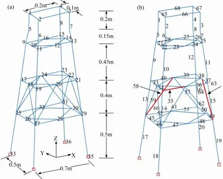
Fig.1 Sketch of the platform model and the element ordering.
3.2 Simulations of Damage Cases
A total of eight damage cases were investigated, as summarized in Table 1. In those cases, structure damages were simulated by reducing the elastic modulus of appropriate members. For example, the damage severity ‘10%’in case 1 indicates a 10% reduction of the elastic modulus E of structural member 63, as shown in Fig.1. The damaged members considered in the damage cases consist of a diagonal brace (member 58) in long-span direction (xbrace 58), a diagonal brace (member 63) in short-span direction (y-brace 63), and a horizontal beam (member 35) in long-span direction (x-beam 35) (Fig.1). The first three damage cases are limited to single damage locations and the other five damage cases deal with multiple damage locations. The first two modal frequencies of undamaged and damaged structures are also listed in Table 1.
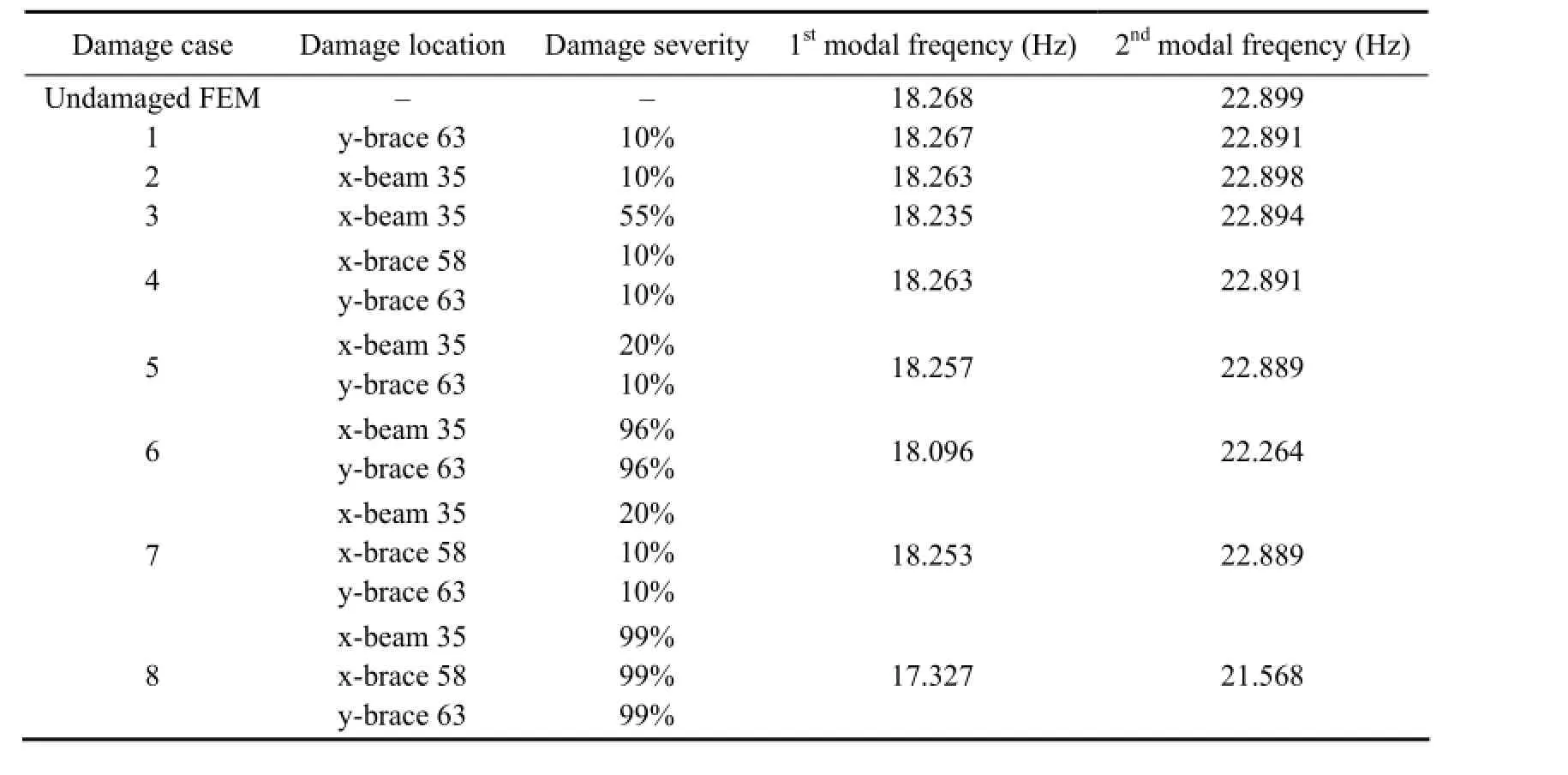
Table 1 Damage scenarios in the numerical study
3.3 Damage Localization
In this numerical example, the first two modes with only translational DoFs of each mode shape are used to investigate the damage localization. In the following damage detection, the modes of undamaged and damaged structures are simulated using a finite element model.
Damage cases 1 to 3 investigate the damage detection for single damage locations. The first damage case is a 10% loss of Young’s modulus for a diagonal brace at member 63 in short-span direction (namedy-brace 63). Fig.2 shows the resulting damage indexes, where the top panel is the Stubbs damage index, and the middle and the bottom panel are the axial and the transverse indexes of the modal strain energy decomposition method, respectively. It can be seen that both Stubbs index and axial index are able to localize the damage correctly. Similar results can be drawn for other damaged braces, such asx-brace 58 (not shown here).
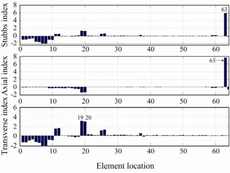
Fig.2 Damage case 1: y-brace 63 is damaged.
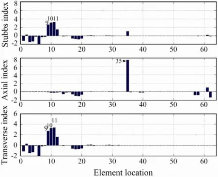
Fig.3 Damage case 2: x-beam 35 is damaged (10%).
Damage cases 2 and 3 investigate the 10% and 55% losses of Young’s modulus of a horizontal beam at member 35 in long-span direction (x-beam 35), respectively. The corresponding damage indicators are shown in Figs.3 and 4, respectively. These figures show that the Stubbs damage indicator is unable to identify the damaged location, missing the potential damagedx-beam 35 for small (10%) damage case and falsifying damage locations for severe (55%) damage case. However, the axial damage indicator of MSED accurately provides the location of the damaged beam for both cases. As shown in Fig.1, larger transverse damage indicators can be seen at elements 9–12, which are column structural members located just above the damage element 35. It is indicated that a damaged horizontal beam member with a large axial damage indicator will have influence on adjacent column elements.
Damage cases 4 to 6 investigate the detection for double damage locations. The damaged members in damage case 4 consist ofy-brace 63 andx-brace 58, both with a 10% loss of Young’s modulus. Fig.5 shows that both methods can correctly locate the damaged diagonal braces even for small damages. Damage cases 5 and 6 investigate the combination of damage members, a beam member (x-beam 35) and a diagonal brace member (y-brace 63), with different severity levels. In case 5, the losses of E forx-beam 35 andy-brace 63 are 20% and 10%, respectively. Fig.6 shows that the Stubbs index misses the damaged horizontal beam member (x-beam 35). In case 6, both beam and brace members are severely damaged. With the loss of Young’s modulus increased to 96%, both Stubbs index and axial index of MSED can be used to localize the horizontal beam members correctly (Fig.7). This demonstrates that it is more difficult to identify a damaged horizontal beam member combined with a damaged diagonal brace. It also shows that the axial damage indicator has the advantage of localizing small damages compared with the Stubbs index method.
Damage cases 7 and 8 investigate the triple damage localization for the potential damaged members,x-beam 35,x-brace 58, andy-brace 63. Case 7 is a light damage case with 20%, 10% and 10% of Young’s modulus loss for these damaged members, respectively. The corresponding damage indexes shown in Fig.8 indicate that the Stubbs index can only identify they-brace 63 damaged location while the axial index can locate all the damages. For a severe damage case with the damage severity of all the members increased to 99%, Fig.9 shows that both theStubbs index and axial index of MSED are capable of localizing the potential damages. From the eight damage cases, it can be concluded that the MSED method outperforms the Stubbs method in locating damaged horizontal beam members and small potential damages for both single and multiple damage cases.
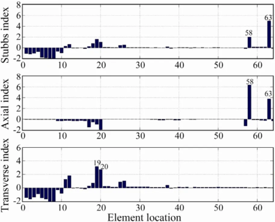
Fig.5 Damage case 4: x-brace 58 and y-brace 63 are damaged.
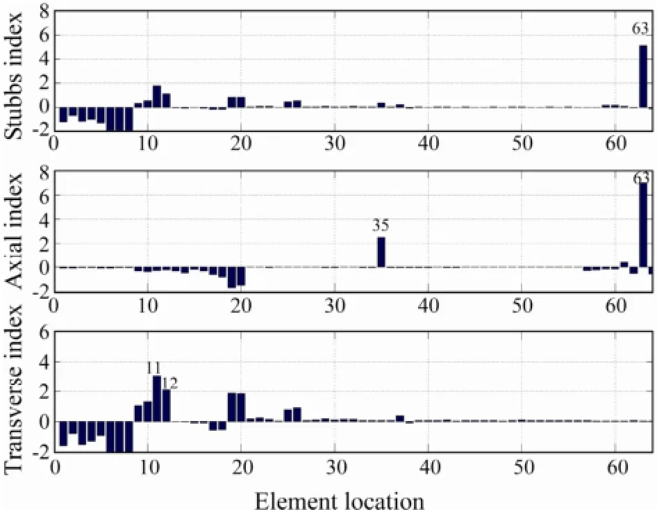
Fig.6 Damage case 5: x-beam 35 (20%) and y-brace 63 (10%) are damaged.
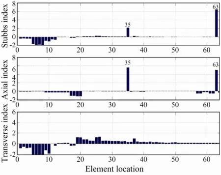
Fig.7 Damage case 6: x-beam 35 (96%) and y-brace 63 (96%) are damaged.

Fig.8 Case 7: x-beam 35 (20%), x-brace 58 (10%) and y-brace 63 (10%) are damaged.
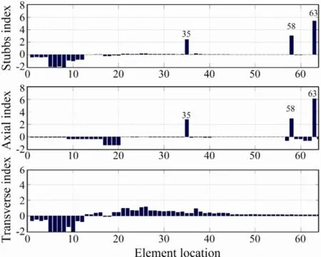
Fig.9 Case 8: x-beam 35 (99%), x-brace 58 (99%) and y-brace 63 (99%) are damaged.
From the numerical study, one can notice that the axial indicator of MSED gives the better damage localization results than the Stubbs index method and the transverse indicator of MSED. And the axial indicator of MSED gives the better results especially for localizing damagedhorizontal-beam-member than the Stubbs damage indicator for both single damage cases and multiple damage case. A short discussion will be given here.
A typical 3D frame structure consists of vertical columns, horizontal beams, and diagonal braces. If the vibration modes used in damage detection are mainly lateral (horizontal) motion, the modal strain energy of vertical members would be dominated by the transverse modal strain energy. On the other hand, the axial modal strain energy would contribute significantly to the modal strain energy of horizontal members and diagonal braces. Therefore, if the damaged member is a horizontal beam and predominant modal strain energy changes take place only in vertical members for the horizontal vibration modes, the damage is unlikely to be detected based on the Stubbs damage index algorithm. In contrast, if the MSED method is applied, a larger axial damage indicator occurs at damaged beams, together with high values of a trans-verse damage indicator for the vertical members connected to the damaged beams.
4 Experimental Validation
4.1 Description of the Offshore Platform Physical Model
The structure is studied by a jacket-type offshore platform model, as shown in Fig.10. The platform model is a welded-steel space frame braced with horizontal and diagonal members with four primary legs. All the members are welded with steel pipes except for the top deck that is a steel plate. The essential geometrical and material properties of the frame structure are given below. Young’s modulus E is a constant equal to 2.1×10¹¹Pa for all members. The primary legs of the model have a diameter of 25 mm and a wall thickness of 2.5 mm. All other members have a diameter of 16 mm with a pipe thickness of 1.5 mm. The deck is a steel plate with a thickness of 12 mm. Other geometrical dimensions are shown in Fig.11.
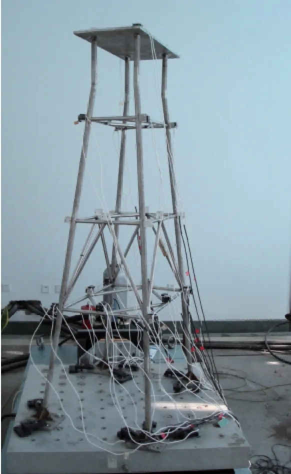
Fig.10 Physical model under test.

Fig.11 Sensor configuration of the model. Red dots indicate sensor locations.
4.2 Experimental Set-Up and Damage Cases
To acquire spatially-complete mode shapes, sensor configuration is partitioned into two phases for a total of 36 accelerometers in laboratory (Fig.11). In the first measurement, sensors are deployed as follows: 1) 12 sensors are installed at nodes 2, 4, 9, 11, 13 and 15, with two sensors at each node to record vibration in x and y directions, respectively. 2) 24 sensors are installed at nodes 17 to 24, with three sensors at each node to record vibration in x, y and z directions, respectively (Fig.11(a)). After one modal test, the 24 sensors at nodes 17 to 24 are moved to the lower level (nodes 25 to 32) while other sensor locations remain unchanged (Fig.11(b)). The model is triggered by an impact hammer which horizontally hits the center of the platform deck. Tests are first performed on the undamaged structure and then repeated for the structure with damaged structural member(s).
Four damage scenarios are simulated in the tests, as listed in Table 2, which include single damage, double damage, and triple damage cases. Damages are simulated in the way that the associated members are damaged by thin saw cut. To study the extent of damage for detection, two levels of damage are specified for the single damage case, a diagonal brace (Member 58) with a one-half hacksaw cut and a full cut through a cross section, respectively.
4.3 Modal Parameter Identification
The Eigensystem Realization Algorithm with the Natural Excitation Technique has been verified to be effective for modal identification based on output-only responses (Wanget al., 2005; Wang and Liu, 2010) and was used to extract modal frequencies and mode shapes ofundamaged and damaged structures. The first three modal frequencies of the undamaged structure and the damage cases are listed in Table 2. The first three identified mode shapes of the undamaged structure are shown in Fig.12. As described in Section 4.2, the mode shapes are synthesized from two modal tests of the undamaged structure due to sensor limitations. It can be seen that the first and second modes show a vibration predominantly inx(longspan) andy(short-span) directions, and the third mode vibrates dominantly aroundzdirection, respectively.

Table 2 Damage cases of the physical model and the first three modal frequencies
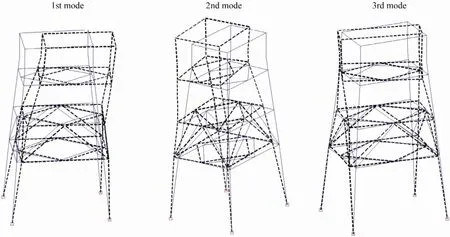
Fig.12 The first three identified mode shapes of the undamaged physical model.
4.4 Damage Localization
Damage cases 1 and 2 investigate the detection for single damage location. In cases 1 and 2,x-brace 58 is damaged with a one half and a full hacksaw cut through the cross section, respectively. The resulting damage indexes are shown in Figs.13 and 14. Identical to the figures in the numerical study, the top panel is the Stubbs damage index, and the middle and bottom panels are the axial and the transverse indexes of the modal strain energy decomposition method, respectively. As shown in Fig.14, both the Stubbs index and MSED method could identify the damage location for the full cut case, but the Stubbs index also presents a false location (element 5). For the half cut case (damage case 1), both methods are unable to detect the damaged location. This is probably because the halfcut damage is too small as listed in Table 2. Compared to errors of the modal testing, the changes in modal parame-ters of the structure are negligible. The combination of damagedx-brace 58 andy-brace 63 is the second damage case investigated. For the third damage case, three damaged members,x-beam 35,x-brace 58 andy-brace 63, are included. The resulting damage indicators are shown in Figs.15 and 16. From these figures, one can see that both the Stubbs index and MSED methods can accurately identify the damage locations.
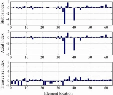
Fig.13 Damage case 1: x-brace 58 is damaged (half cut).
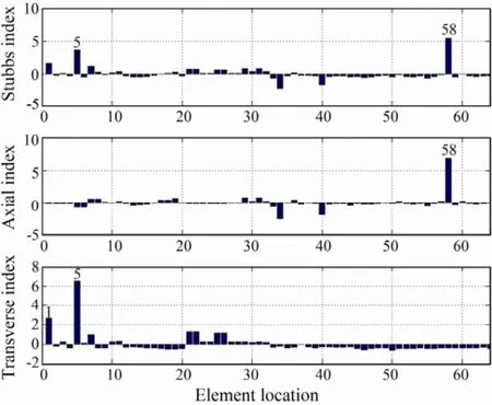
Fig.14 Damage case 2: x-brace 58 is damaged (full cut).
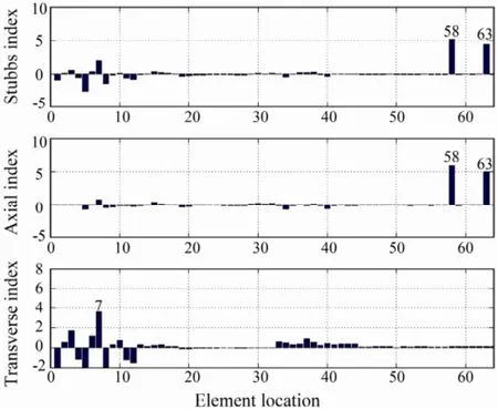
Fig.15 Damage case 3: x-brace 58 and y-brace 63 are damaged.
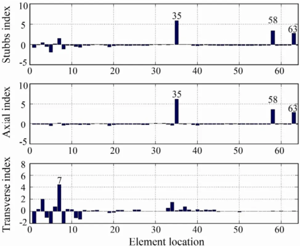
Fig.16 Damage case 4: x-beam 35, x-brace 58 and ybrace 63 are damaged.
4 Conclusions
Damage localization was compared between a traditional modal strain energy method and a recently developed modal strain energy decomposition method using the calculated results and modal testing data. The numerical study was performed considering different levels of damage severity of single and multiple damage scenarios. By building physical models, laboratory data were collected and applied to the damage detection algorithms. Based on the present investigation, the following conclusions could be drawn.
1) The axial indicator of the MSED method is superior to the Stubbs index for localizing damaged horizontal beam member in both single and multiple damage cases. The transverse indicator of the MSED method shows no direct indication of damaged horizontal beam and diagonal braces, but is useful to help identify the potential damaged location(s) for three dimensional structures with braces.
2) Numerical simulations demonstrate that the MSED method outperforms the Stubbs index method for locating small potential damages.
3) Experimental results demonstrate the feasibility of using synthesized mode shapes for damage localization identified from two partial measurements for one damage scenario when the number of sensors is limited for a complete configuration.
4) From the laboratory results of damage localization, both methods can identify the damage locations correctly for severe damage cases, but fail to localize the damages for small damage cases. The results also indicate that the modal parameter identification plays an important role in small damage detection.
Acknowledgements
This work was supported by the National Basic Research Program of China (2011CB013704), 863 project (2008AA092701-5), the National Natural Science Foundation of China (50909088, 51010009, 51379196), and the Program for New Century Excellent Talents in University (NCET-10-0762). The authors would like to express their thanks for the support.
Alvandi, A., and Cremona, C., 2006. Assessment of vibrationbased damage identification techniques. Journal of Sound and Vibration, 292: 179-202.
Choi, F. C., Li, J., Samali, B., and Crews, K., 2007. An experimental study on damage detection of structures using a timberbeam. Journal of Mechanical Science and Technology, 21: 903-907.
Doebling, S. W., Farrar, C. R., Prime, M. B., and Shevitz, D. W., 1998. A review of damage identification methods that examine changes in dynamic properties. Shock and Vibration Digest, 30 (2): 91-105.
Farrar, C. R., and Jauregui, D. V., 1998. Damage detection algorithms applied to experimental and numerical modal data from the I-40 Bridge. Los Alamos National Laboratory Report LA-13074-MS. Los Alamos, New Mexico.
Fukunaga, K., 1990. Introduction to Statistical Pattern Recognition. Academic Press, New York, 51-122.
Hu, H. W., and Wu, C. B., 2009. Development of scanning damage index for the damage detection of plate structures using modal strain energy method. Mechanical Systems and Signal Processing, 23: 274-287.
Kim, J.-T., and Stubbs, N., 2002. Improved damage identification method based on modal information. Journal of Sound and Vibration, 252 (2): 223-238.
Kumar, M., Shenoi, R. A., and Cox, S. J., 2009. Experimental validation of modal strain energies based damage identif ication method for a composite sandwich beam. Composites Science and Technology, 69: 1635-1643.
Li, H. J., Yang, H. Z., and James Hu, S.-L., 2006. Modal strain energy decomposition method for damage localization in 3D frame structures. Journal of Engineering Mechanics, 132 (9): 941-951.
Seyedpoor, S. M., 2012. A two stage method for structural damage detection using a modal strain energy based index and particle swarm optimization. International Journal of Non-Linear Mechanics, 47: 1-8.
Shi, Z. Y., Law, S. S., and Zhang, L. M., 2000. Structural damage detection from modal strain energy change. Journal of Engineering Mechanics, 126 (12): 1216-1223.
Stubbs, N., Kim, J. T., and Farrar, C. R., 1995. Field verification of a nondestructive damage localization and severity estimation algorithm. Proceedings of International Modal Analysis Conference. Society of Experimental Mechanics, Connecticut, USA, 210-218.
Wang, S. Q., and Li, H. J., 2012. Assessment of structural damage using natural frequency changes. Acta Mechanica Sinica, 28 (1): 118-127.
Wang, S. Q., and Liu, F. S., 2010. New accuracy indicator to quantify the true and false modes for eigensystem realization algorithm. Structural Engineering and Mechanics, 34 (5): 625-634.
Wang, S. Q., Li, H. J., and Takayama, T., 2005. Modal identification of offshore platforms using statistical method based on ERA. China Ocean Engineering, 19 (2): 175-184.
Wang, S. Q., Zhang, J., Liu, J. K., and Liu, F. S., 2010. Comparative study of modal strain energy based damage localization methods for three-dimensional structure. Proceedings of the 20th (2010) International Offshore and Polar Engineering Conference. Beijing, 4: 398-403.
Yan, W. J., Huang, T. L., and Ren, W. X., 2010. Damage detection method based on element modal strain energy. Advances in Structural Engineering, 13 (6): 1075-1088.
Yan, W. J., Ren, W. X., and Huang, T. L., 2012. Statistic structural damage detection based on the closed-form of element modal strain energy sensitivity. Mechanical Systems and Signal Processing, 28: 183-194.
Yang, H. Z., Li, H. J., and Wang, S. Q., 2003. Damage localization of offshore platforms under ambient excitation. China Ocean Engineering, 17 (4): 495-504.
(Edited by Xie Jun)
(Received May 03, 2012; revised October 29, 2012; accepted January 14, 2014)
? Ocean University of China, Science Press and Springer-Verlag Berlin Heidelberg 2014
* Corresponding author. Tel: 0086-532-66781672
E-mail: shuqing@ouc.edu.cn
 Journal of Ocean University of China2014年3期
- Journal of Ocean University of China的其它文章
- Dynamic Response Analysis of a Floating Mooring System
- Effects of Sulfate Chitosan Derivatives on Nonalcoholic Fatty Liver Disease
- Combined Action of Uniform Flow and Oscillating Flow Around Marine Riser at Low Keulegan-Carpenter Number
- Laboratory Application of Laser Grain-Size Analyzer in Determining Suspended Sediment Concentration
- Fully Coupled Time-Domain Simulation of Dynamic Positioning Semi-Submersible Platform Using Dynamic Surface Control
- Mean Sea Level Changes near Weizhou Island from 1969 to 2010
