Study of parametric roll in oblique waves using a three-dimensional hybrid panel method*
Min Gu,Shu-xia Bu,Jiang Lu
Jiangsu Key Laboratory of Green Ship Technology,China Ship Scientific Research Center,Wuxi 214082,China
Abstract: A reliable numerical tool for the prediction of the parametric roll is important in the development of the second generation intact stability criteria.The main difficulty of the prediction of the parametric roll comes from the significant coupling of the roll with other motions,especially the heave and pitch motions.In this paper,the numerical method for determining the parametric roll is studied and the results are benchmarked against the model test data.Firstly,a 3 degrees-of-freedom (DOF) time domain hybrid panel method is validated by experimental data in regular oblique waves and irregular head waves.Secondly,the verified 3DOF method is extended to a fully coupled 6DOF method with the course control.Finally,taking the C11 containership as the test case,the parametric roll in oblique waves is computed,and the effects of the surge,sway and yaw motions on the parametric roll are evaluated with the developed mathematical models.The results show that the effects of the surge and sway motions on the parametric roll is insignificant,while the effects of the yaw motion are more notable.The results of the roll amplitudes and the standard deviation of the roll angles show that the model based on 3DOF gives relatively conservative results,and can be directly used for the stability assessment of the parametric roll.
Key words: 6DOF mathematical model,irregular oblique waves,second generation intact stability in IMO
Introduction
As one type of the large amplitude roll motions,the parametric roll has been well known since the severe parametric roll accident of the C11 class post Panamax containership in 1998[1],and it is one of the most stringent phenomena for ships sailing in seas.Currently,the second generation intact stability criteria are under development by International Maritime Organization (IMO)[1-2].
According to the proposed drafts,the multi-level structure is adopted to make sure that the numerical assessment procedures are only applied when the vulnerability to the dynamical stability failures is beyond reasonable doubt.The judgement of the vulnerability criteria of the parametric roll is basically deterministic.Only simplified geometry characteristics or empirical formulas are used[3].However,the direct stability assessment requires a highly accurate prediction,taking all the wave directions into consideration.
Up to now,most of the studies of the direct assessment of the parametric roll focused on the head and following seas.The 3DOF mathematical model taking the heave and pitch motions into account proposed by IMO[4]was widely studied[5-9],The feasibility of this 3DOF mathematical model in the head and following seas has been validated,as also in our previous studies[10].However,in oblique waves,the forces and the moments acting on the hull are asymmetric,and the rudder action is difficult to handle.To the authors’ knowledge,it is not well studied how to simulate the parametric roll in oblique waves,or how to choose a suitable mathematical model for the prediction of the parametric roll in oblique waves,especially in irregular oblique waves.For instance,Umeda et al.[11]studied the parametric roll in regular oblique waves of the ONR flared topside vessel using a coupled 5DOF mathematical model but without the surge motion based on the 2-D strip theory.
In this paper,a fully coupled 6DOF mathematical model is used for the prediction of the parametric roll in both regular and irregular oblique waves based on a three dimensional time domain hybrid panel method.The effects of the surge motion,the sway motion and the yaw motion on the parametric roll are studied.
1.Mathematical model
1.1 3-D hybrid time domain panel method
The parametric roll may occur in the head,following or oblique seas when the encounter frequency is approximately two times the ship roll natural frequency and the roll damping of the ship is insufficient to dissipate the rolling energy.Several methods were developed for the assessment of the parametric roll,such as the 2-D strip theory and the three-dimensional panel methods with the Rankine source or with the free surface Green function,and several critical factors for the assessment of parametric roll were also studied[12-15].
In this paper,a hybrid source method using both the transient Green function and the Rankine source is adopted for the calculation of the parametric roll.The fluid field is split into two domains as shown in Fig.1.TheO-XYplane of the earth coordinate systemO-XYZis at the mean free surface andZ-axis is positive up.The origin of the body coordinate systemG-xyzis fixed at the center of gravity of the ship wherex-axis is positive towards the bow andz-axis positive up.The reference coordinate systemo′ -x′y′z′ moves with the hull,and coincides with the earth coordinate system at the initial time.
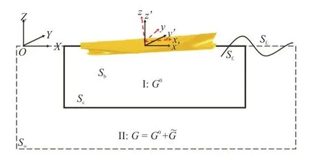
Fig.1 (Color online) Mixed source formulation of panel method
The angleχ=0° is defined when the wave has the same direction as that of the ship (the following wave),that is to say,the wave propagates to the stern.The head wave is defined when the angle (χ) is equal to 180°,namely,the wave propagates to the bow.
The inner domain (I) problem is solved by the Rankine sources within the domain enclosed by the wetted body surfacesSb,one part of the free surfaceSf1near the body,and an outer control surfaceSc.The outer domain (II) problem is solved with the transient Green functions distributed over the control surface,S∞,the imaginary surface at infinity.
The advantage of this method is that Rankine sources are more generic than the transient Green functions near the body and the free surface,and the control surface can be selected to ensure correct numerical behaviors of the solutions.The transient Green functions satisfy both the linearized free surface boundary condition and the radiation condition,allowing the control surface to be placed close to the body.
In the inner fluid field,the total disturbance velocity potential satisfies the following conditions[16]:
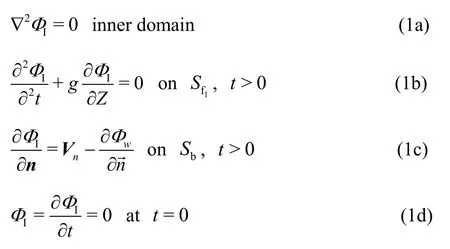
The boundary integral equation in terms of the Rankine sources is expressed as

whereΦIis the disturbance velocity potential in the domain I,G= 1/rpqis the Green`s function,withp(X,Y,Z) denoting the field point andq(ξ,η,ζ)denoting the source point.The boundary condition of the inner field consists of three parts:
In the outer fluid field,the total disturbance velocity potential satisfies the following conditions:
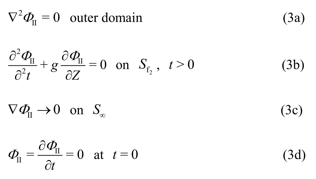
The boundary integral equation in terms of the transient Green’s function is written as

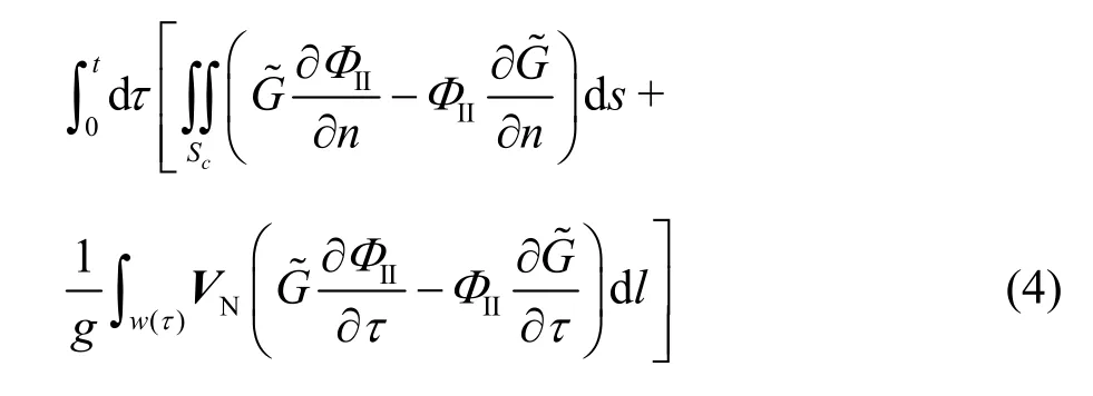
whereΦIIis the disturbance velocity potential in the domain II,G0andare associated with the transient Green`s function,as expressed in Eq.(5),w(τ) is the water line of the control surface,VNis the outward normal velocity ofw(τ) relative to the domain I.The control surfaceScmoves with the body.

On the control surfaceSc,the disturbance velocity potentials in the inner and outer domains are continuous,as well as their normal derivatives.

The discretized form of the integral equation in the inner fluid field can be expressed as

The influence matrices are:
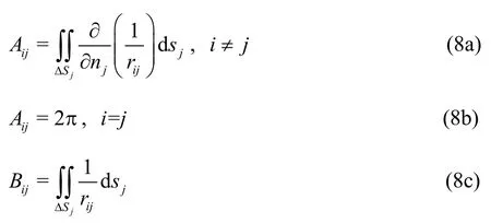
The discretized form of the integral equation in the outer fluid field is

The influence matrices are
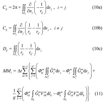
wherem,Mare the indices of the history timeτand timet.
After obtaining the total disturbance potential,the total hydrodynamic pressure can be calculated by the Bernoulli’s equation

In the simulation,the second order drift forces/moments due to the first order potential are considered in order to be more consistent with the actual physical model.
Then the forces on the body are obtained by integrating the above equation over the submerged hull

1.2 Coupled mathematical model
For the numerical simulation of the parametric roll in oblique waves,in addition to the strong coupling among the heave,roll and pitch motions,the effects of the surge,sway and yaw motions also need to be considered.Therefore,the nonlinear fully coupled surge-sway-heave-roll-pitch-yaw mathematical model is used to calculate the ship motions in oblique waves.

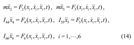
wheremis the ship mass,I44is the inertia of the roll moment,I55is the inertia of the pitch moment,I66the inertia of the yaw moment,Tis the thrust forces,Ris the drag forces,Fiis the force or moment in theidirection,modelled with the following equation

whereFHis the hydrostatic forces,FFKis the Froude-Krylov forces,FRis the radiation forces,FDis the diffraction forces,FSis the second order forces,FGis the gravity andFextis the external forces.
In the numerical simulation,both the hydrostatic forces and the FK forces are calculated by integrating the incident wave pressure on the instantaneous wetted hull surface.The radiation and diffraction forces/moments are calculated using the body linear formulation of the boundary-value problem.Therefore,the above four components obtained from the integration of the pressure on the surface of ship can be rewritten as follows
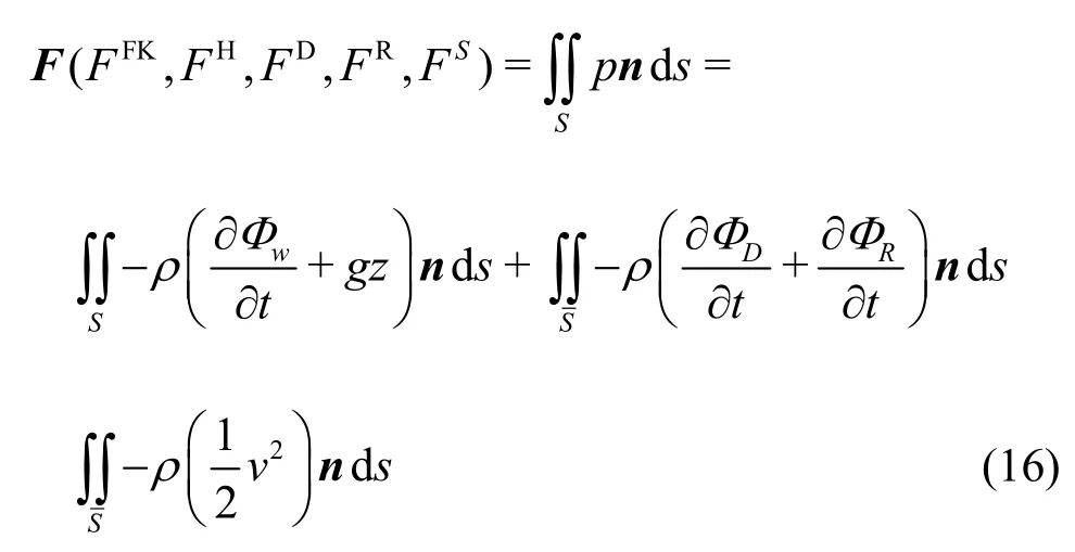
whereSdenotes the instantaneous wetted hull surface,denotes the average wetted hull surface.
The roll restoring arm induced by the Froude-Krylov forces and the hydrostatic forces (GZFH),the radiation and diffraction forces (GZRD)and the second order forces (GZS) can be calculated as


The nonlinear damping coefficients are used,in view of the fact that the parametric roll is sensitive to the viscous effect.The inertial moment and the damping in the roll direction are estimated as follows:

In order to model the surge motion,enough propulsive forces should be applied at the center of the gravity to balance all other axial forces.The desired thrust on the hull is estimated by an empirical formula as

whereFris the Froude number,Fis the thrust equation,which is relative to the unit speed and acceleration,Uis the ship speed andfdis the drag coefficient.

wherex1is the instantaneous position of the forward ship,in which the relative position of the ship and the wave are considered.
The total drag on the hull is estimated by an empirical formula as

1.3 Course control methods
When a ship sails in oblique seas,the forces on the ship are asymmetric.In order to avoid the divergence of the ship motion,the control method should be used to keep the ship on the desired course.In this paper,two methods (the PD autopilot control method and the “soft-spring” control method by adding external restoring force/moment) are used for the control of the sway and yaw motions.
In the PD autopilot course control method,the standard PD algorithm is used

whereKPis the gain coefficient for the proportional term,KDis the gain coefficient for the derivative term,TEis the constant coefficient for the rudder,ris the velocity of the yaw motion,χis the ship heading,χCis the desired ship heading andδis the rudder angle.
Then the force and the moment induced by the rudder can be expressed as:

whereARis the total area of the rudder,xRis the longitudinal rudder position,Cαis the hydrodynamic rudder lift slope,andu: the effective velocity related to lift force.
In the soft-spring control method,the external restoring forces on the sway motion and the moments on the yaw motion are added by the following linear spring terms:

whereK2andK6are the linear spring terms in the sway and yaw directions,respectively.In order to avoid the disturbance of the spring system on the ship motion,the linear spring coefficients are chosen to ensure that the roll period of the whole spring system is 10 times the roll natural period of the ship.
1.4 Seaways and statistical analysis
A linear superposition of the sinusoidal wave components is used.The free surface elevation for the seaway defined with respect to the earth coordinate systemO-XYZ(Fig.1) can be expressed as

The incident wave velocity potential can be written as

whereAi,ki,ωei,εiandβiare the amplitude,the wave number,the encounter wave frequency,the phase angle and the heading angle of theithwave components,respectively.εi= 2πPi(Piis the random number generator,taking a value between 0-1).
Dividing the wave spectrum intoNsegments,the corresponding wave amplitude can be expressed as

In this paper,the ITTC double parameter spectrum is used

whereH1/3is the significant wave height,T01is the mean wave period andωis the wave frequency.
The following equations are used for the calculation of the mean value and the standard deviation of the random sequence (short for STD) in the statistics analysis:
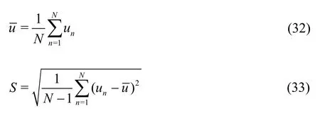
whereis the mean value of the sample signal,unis thenthvalue in the sample signal,Nis the total number of the sample signals andSis the standard deviation of the sample signals.
2.Ship geometry and experiments
In order to validate the numerical method for the parametric roll,the free running model test of the international standard model of C11 containership with a scale 1:65.5 is carried out in the sea keeping basin (length: 69 m,breadth: 46 m and depth: 4 m) of China Ship Scientific Research Center.The basin is equipped with flap wave makers on the two adjacent sides of the basin.The principal particulars of the ship are shown in Table 1,and the hull geometry is shown in Fig.2.
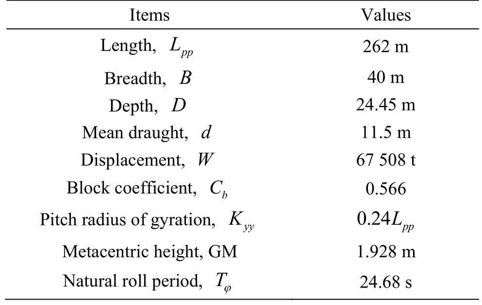
Table 1 Principal particulars of C11 Containership (Scale:1/65.5)
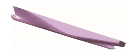
Fig.2 Hull geometry of C11 Containership
Before the free running model test for the parametric roll,the free roll decay tests are carried out to determine the linear and cubic roll damping coefficients.Previous studies show that the parametric roll is of “non-ergodicity”[17-18].The present sea keeping basin is not long enough,and the method of the wave truncation,usually used in sea keeping model tests,cannot be used for the model test of the parametric roll.Therefore,the model tests are carried out in oblique regular waves with different wave slopes.The ship model in the free running model tests is shown in Fig.3.
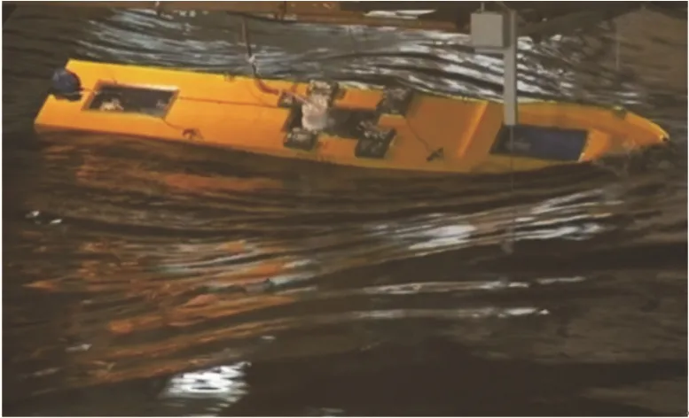
Fig.3 (Color online) Ship model in the free running experiment
3.Numerical simulation
In the simulation,the geometry of the panels is shown in Fig.4.The panels of linear order are used.The boundaries of the inner fluid domain are enclosed by the control surface (dimensions: 1.5Lpp× 4 .0B×4.5d).The ship main section is located at the center of the inner fluid domain.The full scale is used in the numerical simulation.For the simulation in regular waves,at least ten steady periods are taken in the calculations.In the case of the simulation in irregular waves,one hour is taken.The roll angle 1° is used as the initial conditions.

Fig.4 (Color online) Hull panels in simulation
4.Results and discussions
4.1 Results in oblique regular waves
The numerical simulation results for the parametric roll in oblique regular waves calculated with the 3-D time domain panel method are shown in Fig.5,where “φamp” represents the amplitude of roll motion.It is shown that all the simulated results agree well with the experimental results.Under the wave conditionH/λ= 0.02,a discrepancy is found between the numerical simulation results and the experimental results.This is because that the case ofH/λ= 0.02 is the onset of the parametric roll and it is very sensitive to other influencing factors,such as the roll damping and the wave height.The discrepancy narrows when the wave slope is increased to 0.022.Except this case,the prediction accuracy keeps stable within the sensitive range for the parametric roll.It can be concluded that the three dimensional time domain hybrid panel method can predict the parametric roll very well.
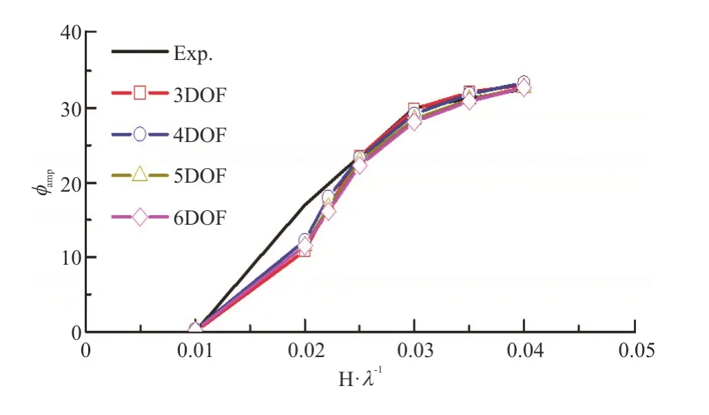
Fig.5 (Color online) Comparison of roll amplitudes calculated by different mathematical models (λ/Lpp =1.0,H/λ= 0.03,Fr=0.1,χ=150°)
In addition,the roll amplitudes calculated by different mathematical models show almost no difference between each other.Notice that the results calculated by 3DOF method are almost the same as those calculated by other models (the 4DOF model further considers the sway motion,the 5DOF model further considers the sway and yaw motions,and the 6DOF model further considers the surge,sway and yaw motions).Therefore,the effects of the surge,sway and yaw motions on the parametric roll are negligible.
One wave condition is chosen to further compare the experimental and computed roll and pitch motions in the time and frequency domains.
Figure 6(a) shows the roll motion in the time domain.The results show that the roll motion is almost the same as those calculated by different mathematical models.
Figure 7(a) shows the FFT curves of the roll motion.The results show that the roll period is twice the pitch period,and almost twice the ship natural roll period.Thus the motion can be judged as a typical parametric roll.
Figure 6(b) displays the pitch motion in the time domain.The experimental results show that the large and small amplitudes appear alternately,which seems like the “subharmonic pitch”.This phenomenon was reported in our previous paper[12].For the simulation results,only 5DOF-S (surge-sway-heave-roll-pitch)and the 6DOF (surge-sway-heave-roll- pitch-yaw)models give a similar tendency as in the model tests.
Figure 7(b) displays the pitch motion by the FFT analysis.The experimental results show that the pitch motion has components of both the half encounter wave frequency and the encounter wave frequency when the parametric roll occurs.The frequency of the subharmonic signal is about half of the encounter wave frequency.However,the component of the sub-harmonic pitch is not obvious in the numerical simulation,which needs further studies.
4.2 Results in oblique irregular waves
4.2.1 Validation in irregular waves
The ITTC double parameter spectrum is adopted for the numerical simulation of the parametric roll in irregular waves,and different random wave seeds are generated in the numerical simulation with consideration of the “non-ergodicity” of the parametric roll.The comparisons of the wave spectrums simulated by the present method and the target wave spectrum show that the codes can reproduce the wave spectrum very well,as shown in Fig.8.
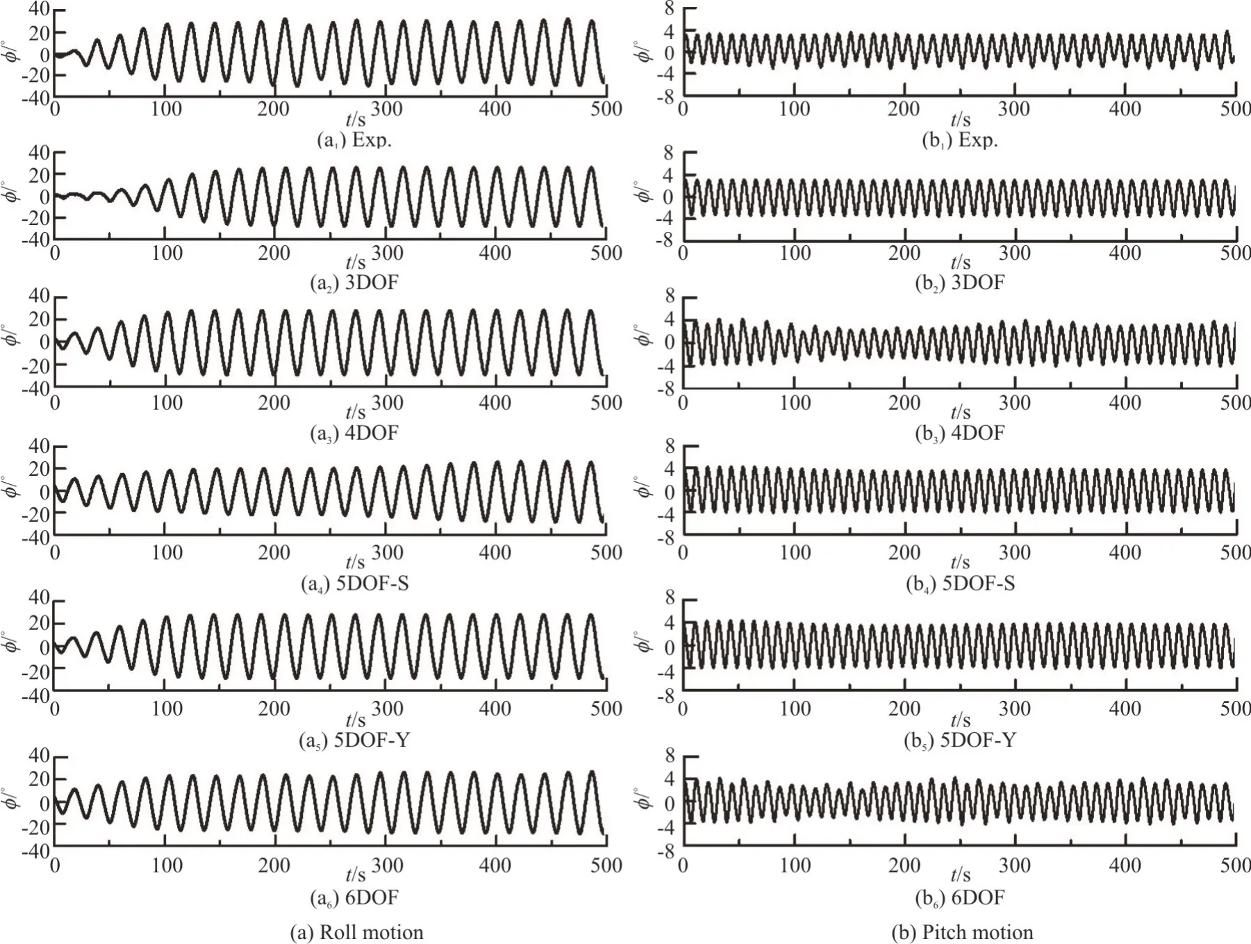
Fig.6 Comparison of time history of roll and pitch motions (λ/Lpp =1.0,H /λ= 0.03,Fr=0.1,χ=150°)
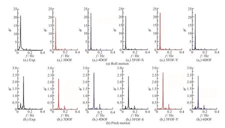
Fig.7 (Color online) FFT comparisons of roll and pitch motions (λ/Lpp =1.0,H /λ= 0.03,Fr=0.1,χ=150°)
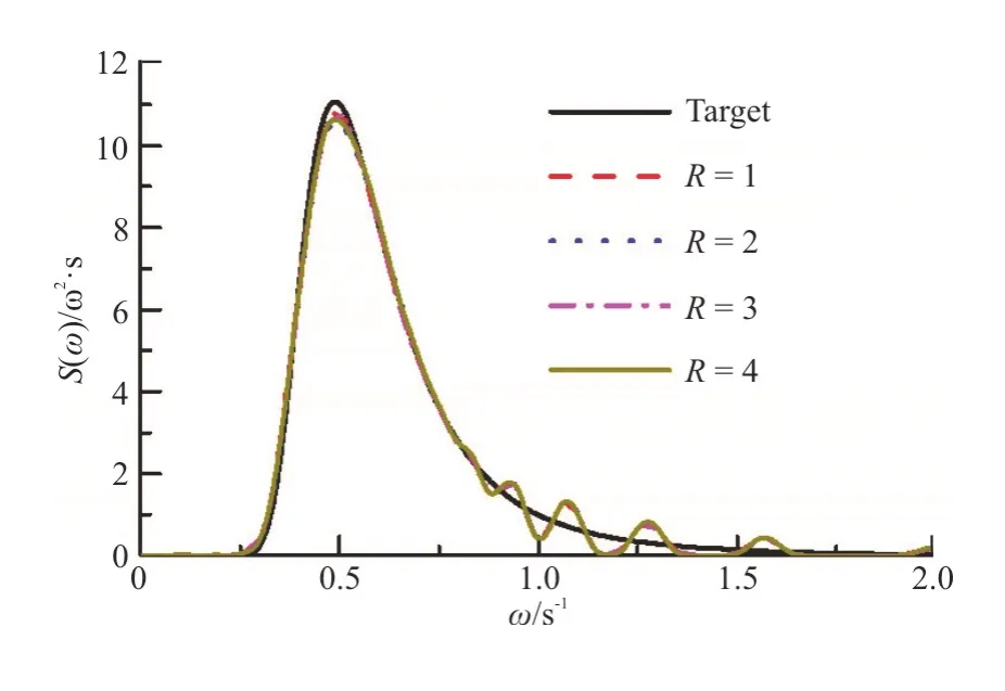
Fig.8 (Color online) Wave spectrums with different realization numbers
As one of the international standard models for the parametric roll,the model tests for C11 class post Panamax containership were conducted by a few organizations.For the parametric roll in irregular waves,Hashimoto and Umeda from Osaka University conducted experimental tests[19].In this paper,the results of the three-dimensional panel method for the parametric roll in irregular waves are validated with their experimental results.Two wave conditions are selected,and the comparisons of the results are shown in Fig.9,where the symbol “No.” represents the random wave seeds.It demonstrates that the numerical method can predict the parametric roll both in regular waves and irregular waves,which has also been confirmed in our previous studies[10].
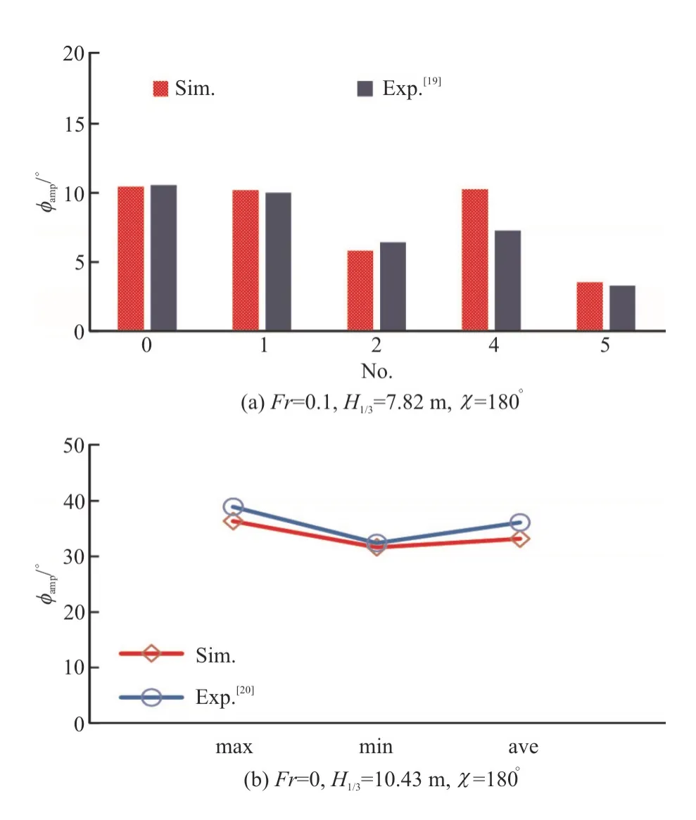
Fig.9 (Color online) Comparison of maximum roll angles between simulation and experiment[19-20]
4.2.2 Effects of different motions on parametric roll
The parametric roll in oblique irregular waves is further studied using the above method.The comparisons of the roll amplitude and the standard deviation of the roll angles of different freedoms are shown in Fig.10,where “φSTD” stands for the standard deviation of roll.
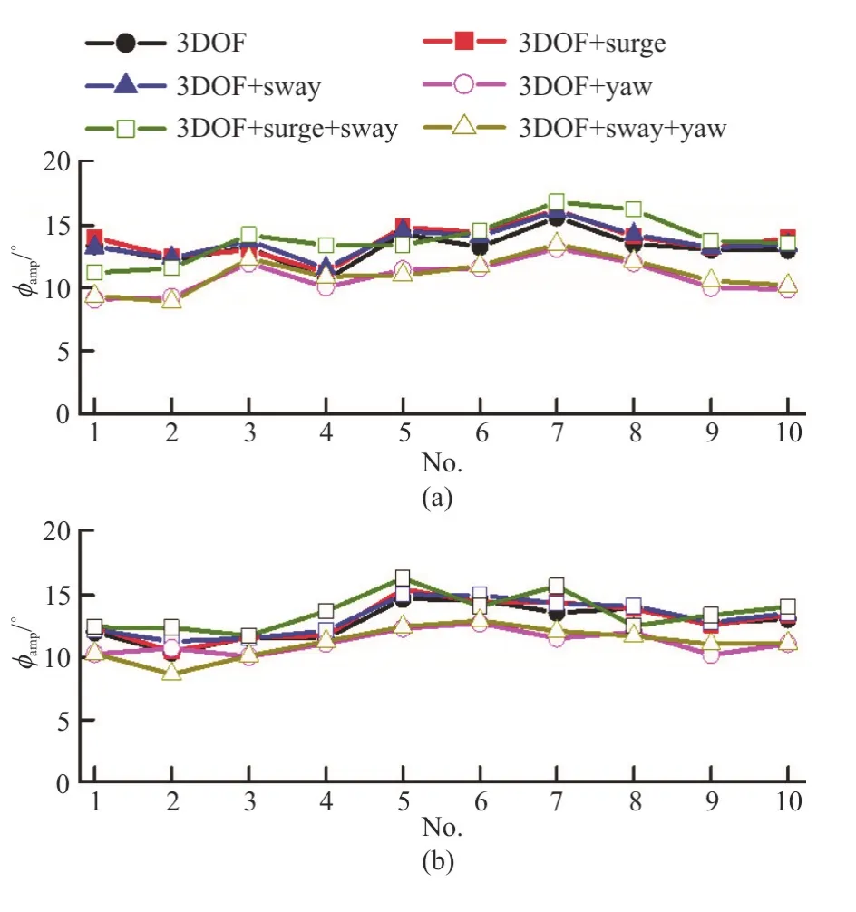
Fig.10 (Color online) Comparisons of roll amplitude and standard deviation of roll of different freedoms for different wave seeds (H1/3=7.82 m ,T01=9.99s ,Fr=0.1,χ=150°)
When the surge motion is taken into account,the roll amplitudes and the standard deviation of the roll angles are slightly larger than those without the surge motion,but the difference is small (Fig.10).Figure 11 shows the ship velocity and the forward distance of the surge motion.It is found that the forward speed varies periodically around the initial speed.However,the advancing distance of the ship is not affected by the periodical variation of the velocity when the surge motion is considered,maybe due to the averaging effect of the varying velocities.Figure 12 further shows the influence of the surge motion on the roll-restoring variation,as the main reason for the occurrence of the parametric roll.In this figure,the symbol “GZFH” represents the roll restoring arms,produced by Froude-Krylov and hydrostatic roll moments,“GZFH+RD” represents the roll restoring arms calculated by Froude-Krylov,hydrostatic,radiation and diffraction moments,“GZFH+RD+S”stands for the second order moments included in the calculation of roll restoring arms,“φc” stands for the constant heeling angle.Different components of the roll-restoring variation are studied.The results show that there is a good consistency between the roll restoring variations with and without taking the surge motion into consideration.Based on the above discussion,it can be therefore concluded that the effect of the surge motion on the parametric roll is negligible.This finding is similar to that made in our previous studies in regular and irregular head waves[20].
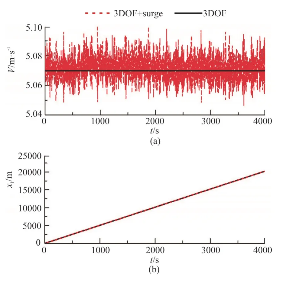
Fig.11 (Color online) Ship velocity and forward distance of surge motion (H1/3=7.82 m ,T01=9.99s ,Fr=0.1,χ= 150°)
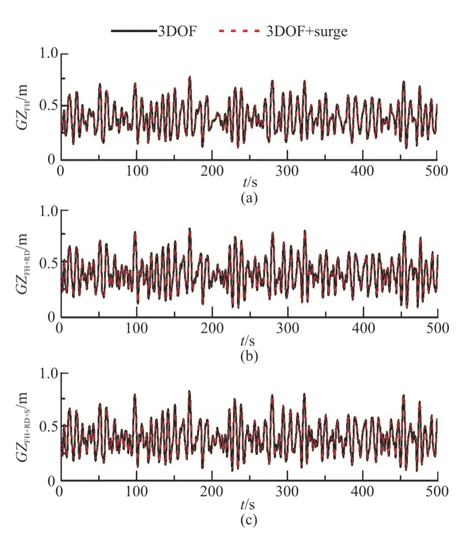
Fig.12 (Color online) Comparisons of roll-restoring variations with and without surge motion (H1/3=7.82 m,T0 1 =9.99s,Fr=0.1,χ=150°,φc=10°)
Although the effect of the surge motion on the roll amplitudes is negligible,the phenomenon of the“sub-harmonic pitch” motion is observed in regular oblique waves when the surge motion is considered,as shown in Fig.7,however,it is not observed in other mathematical models when the surge motion is not considered.It seems that the surge motion could influence the pitch motion,which needs further studies.
When the sway motion is taken into account,the roll amplitudes and the standard deviation of the roll angles are slightly larger than those without the sway motion (Fig.10).Figure 13 shows the ship motion when the wave random seed is equal to 1 with and without the sway motion,where “x2” denotes sway motion,“ζ” denotes heave motion,“φ” denotes roll motion,“θ” denotes pitch motion.Since the second order drift forces/moments are considered,the relative position between the wave and the ship will change in oblique waves due to the drift in the transverse direction.However,the change has no effect on the heave,roll and pitch motions.
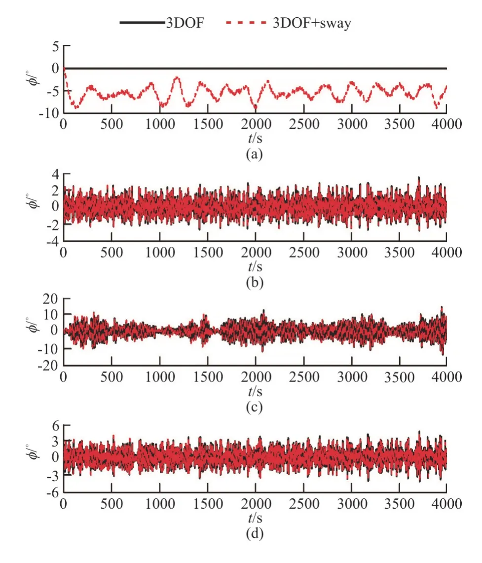
Fig.13 (Color online) Comparisons of history records with and without sway motion (H1/3=7.82 m,T01=9.99s ,Fr = 0.1,χ=150°,No.1)
Figure 14 shows the comparisons of the different components of the roll-restoring variations in cases of constant heeling angles (φc) 10° with and without sway motion.It can be seen that there are almost no differences when the sway motion is considered.Therefore,it can be concluded that the effect of the sway motion on the parametric roll is also negligible.
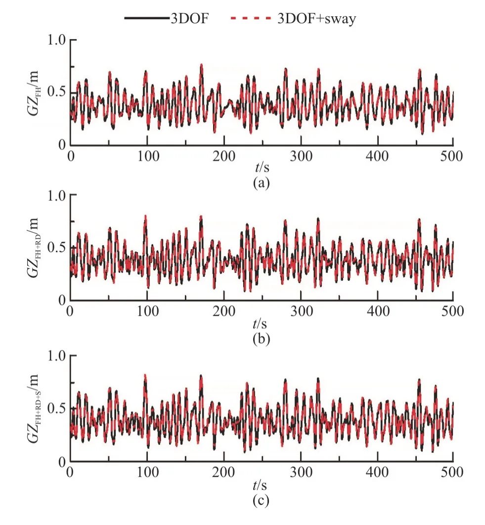
Fig.14 (Color online) Comparisons of roll-restoring variation with and without sway motion (H1/3=7.82 m,T0 1 =9.99s,Fr=0.1,χ=150°,φc=10°)
Unlike the surge and sway motions,it is found that the effect of the yaw motion on the parameter roll is not negligible.The comparison results show that the results with the yaw motion are smaller than those without the yaw motion (Fig.10).It seems that the yaw motion tends to reduce the parametric roll.
Figure 15 shows the ship motion when the wave random seed is equal to 1 with and without the yaw motion,where “x6” denotes yaw motion.It can be seen that the effect of the yaw motion on the parametric roll is noticeable.The ship heading angle varies around the initial heading angle when the yaw motion is taken into account,which will consequently change the encounter wave frequency.The shift of the encounter frequency will further lead to the change of the roll-resorting variation in the amplitudes and frequencies,due to some energy transferred from the roll to the yaw motion.
Figure 16 show the simulation results of the roll-restoring variations in cases of constant heeling angles (φc) 10° and -10°.A discrepancy is seen between the calculated results at different heeling angles,maybe due to the asymmetrical forces imposed by oblique waves on the hull.The amplitudes and the frequencies of the roll restoring variations are changed due to the yaw motion at both the investigated heeling angles,indicating that the yaw motion can affect the parametric roll.
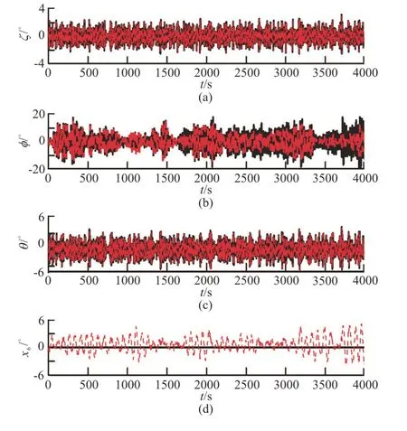
Fig.15 (Color online) Comparisons of history records with and without yaw motion (H1/3=7.82 m,T01=9.99s ,Fr = 0.1,χ=150°,No.1)
Figure 10 also shows the coupled effects of the surge and sway motions on the roll amplitudes and the standard deviation of the roll angles.The results show that the variations of the results are very small when both the surge and sway motions are taken into account.This is easy to understand,since we have found that the effects of the surge and sway motions on the parametric roll are very small.Figure 17 shows the comparison of different components of the roll restoring arm variation calculated by different mathematical models.It can be seen that the coupled effects of the surge and sway motions are also negligible.
The results of the coupled effects of the sway and yaw motions on the parametric roll (Fig.10) show that the parametric roll is reduced when both the sway and yaw motions are taken into account.With coupled sway and yaw motions,the roll amplitudes and the standard deviation of the roll angles vary in a similar way as those with the yaw motion,owing to the fact that the sway motion has little effect on the parametric roll.
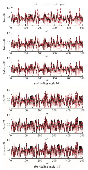
Fig.16 (Color online) Comparisons of roll-restoring variation with and without yaw motion (H1/3=7.82 m ,T01=9.99s,Fr=0.1,χ=150°)
In order to determine the accurate differences between different mathematical models,we consider the maximum and standard deviations of the roll with different wave seeds from the largest to the smallest.Figure 18 shows the maximum roll angles and the standard deviation of the roll angles calculated by different mathematical models,where the symbol “N”denotes the sorted number of wave seeds.“3DOF”denotes heave-roll-pitch model,“4DOF” denotes sway-heave-roll-pitch model,“5DOF (surge)” denotes surge-sway-heave-roll-pitch model,“5DOF” denotes sway-heave-roll-pitch-yaw model,“6DOF” denotes surge-sway-heave-roll-pitch-yaw model.We can see that the roll amplitudes are reduced when the yaw motion is taken into account.However,the overall differences of the roll amplitudes using different mathematical models are less than 3.5°.The overall differences of the standard deviation of the roll angles are less than 0.8°.Obviously,the differences of the maximum roll angles and the standard deviation of the roll angles are both acceptable in engineering applications.This indicates that the 3DOF mathematical model for the direct stability assessment of the parametric roll proposed by IMO in the second generation intact stabi-lity is relatively conservative,thus the mathematical model can be used for the development of the parametric roll stability criteria.
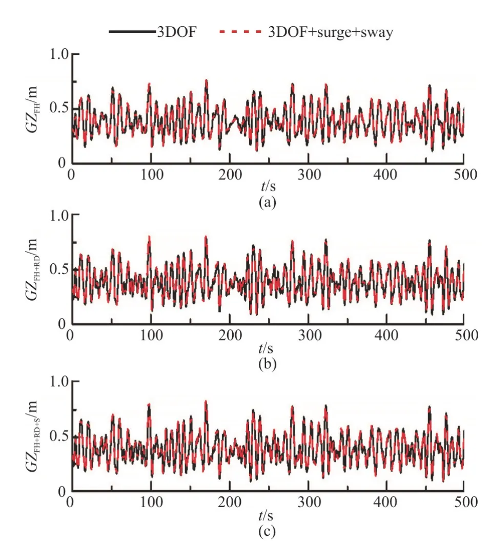
Fig.17 (Color online) Comparisons of roll-restoring variations with and without surge and sway motions (H1/3=7.82m,T01=9.99s ,Fr=0.1,χ=150°,φc=10°)
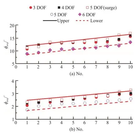
Fig.18 (Color online) Maximum roll angles and standard deviation of roll calculated by different mathematical models (H1/3=7.82 m,T01=9.99s ,Fr=0.1,χ= 150°)
4.2.3 Effects of course control method The course control method has a significant effect on the ship heading,which further affects the yaw motion.Therefore,we compare the results obtained by using two conventional course control methods.Figure 19 shows the results calculated by two course methods,where “-PD” stands for the PD course control method and “-Soft” soft-spring control method.Little discrepancy is seen between this two course methods.
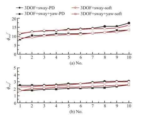
Fig.19 (Color online) Comparisons of PD and soft-spring control methods (H1/3=7.82 m ,T0 1 =9.99s,Fr=0.1,χ= 150°)
5.Conclusions
This paper studies the parametric roll in regular and irregular oblique waves using a 3-D hybrid panel method.The following conclusions are drawn:
(1) 3-D time domain hybrid panel method can be used for the prediction of the parametric roll in regular and irregular oblique seas.
(2) The effects of the surge and sway motions on the parametric roll are relatively small.Thus,the surge and sway motions can be ignored if a simplified model of the parametric roll is to be used.
(3) The yaw motion reduces the parametric roll.However,its effect is marginal.The 3DOF mathematical model proposed by IMO in the second generation intact stability for the parametric roll stability failure mode is slightly conservative,thus can meet the requirement of engineering applications.
The effects of the surge motion on the parametric roll are relatively small and can be ignored.However,the phenomenon of the “sub-harmonic pitch” motion is reproduced in regular oblique waves when the surge motion is taken into account,which needs further investigations.
Acknowledgement
The C11 containership used in this paper is provided by IMO correspondence group for the study of second generation intact stability.The authors would like to extend their sincere gratitude to the aforementioned organizations.
 水動(dòng)力學(xué)研究與進(jìn)展 B輯2020年1期
- 水動(dòng)力學(xué)研究與進(jìn)展 B輯的其它文章
- Numerical simulation of condensation shock in partial cavitating flow on a hydrofoil*
- Flow regime and energy dissipation of SFS-type flip buckets*
- Spatial and spectral investigation of turbulent kinetic energy in cavitating flow generated by Clark-Y hydrofoil*
- A design of T-foil and trim tab for fast catamaran based on NSGA-II*
- Adaptive mesh refinement immersed boundary method for simulations of laminar flows past a moving thin elastic structure*
- Reconstruction of 3-D surface waves generated by moving submerged sphere based on stereo imaging principle*
