Reconstruction of 3-D surface waves generated by moving submerged sphere based on stereo imaging principle*
Xin-long Wang,Gang Wei,Hui Du,Shao-dong Wang
Department of Meteorology and Oceanography,National University of Defense Technology,Nanjing 211101,China
Abstract: A sailing ship can produce significant disturbances on the water surface,but the perturbation generated by a moving submerged source is much smaller due to the physical property of the free surface,as represented by the rigid-lid assumption,with the geometric displacement barely observed or measured.Based on the stereo imaging principle,an experimental system for the three-dimensional measurement of the surface perturbation is built by assembling two charge coupled device (CCD) sensors,to measure the surface waves generated by a small submerged sphere,including the small-scale vertical displacements and the flow field on the water surface.The obtained results are consistent with those obtained by the theoretical analysis,and the measurement accuracy for the vertical displacements is improved by 50% compared to that of the direct optical method based on the image grey levels.Additionally,the present measurement technique can be efficiently and precisely applied to other measurements of small-scale disturbances on a free surface.
Key words: Surface wake,stereo imaging,geometric reconstruction,particle image velocimetry (PIV)
Introduction
A train of gravity waves generated by an object moving at a constant speed on the water surface or underwater is well known as the Kelvin wake.It was early proved that the wake is always delimited by the Kelvin angle,based on the stationary phase method or the geometric ray theory[1].Further studies revealed that two sets of waves in the wake can be distinguished,i.e.,the so-called transverse waves and the diverging waves.Recently some observations show that the wake angle may decrease as the Froude number (Fr) increases[2].To meet the need for the surface ship monitoring,and especially for the underwater submarine detection,the hydrodynamic wake structure of the submerged objects s attracted much research attention in recent decades.Because the existing acoustic detection methods could not satisfy the demand of the continued development of submarine noise reduction technologies,new and more effective detection methods must be adopted as auxiliary technologies.Various remote sensing detections can effectively monitor the surface waves generated by a ship or a submarine.These methods are much more convenient than the acoustic detections in a wider detection range in view of the large spatial scale of the wake compared to the dimensions of the submarine itself.The surface wake structure characteristics are of great significance for the detection of underwater moving objects,and the laboratory measurements in a tank for the perturbation structure on the water surface play an important role in studying the wake and its evolution.Recently,different optical methods for surface measurements were applied to free surface waves[3].
Advanced optical methods for surface measurements are widely used in wave experiment measurements[4-5].Tsubaki and Fujita[6]proposed a stereovision measurement technique to reconstruct the small amplitude surface waves by making the water white so the water surface would appear as a solid surface when they project an irregular pattern using an liquid crystal display (LCD) projector.Douxchamps et al.[7]developed a stereoscopic measurement system by using the refractive properties of the water to reconstruct the surface of an antidune flow based on the imaging of floating tracers dispersed on the rapidly flowing surface.Du et al.[8]attempted to measure the small-scale vertical displacement of the surface wake by using a direct optical method with a single linear array charge coupled device (CCD) and reconstructed its 3-D structure with the grey level information in a time series.However,the surface velocity field cannot be measured using this method,and the higher accuracy achieved in measuring a small-scale displacement is not satisfactory because the grey levels of the image are easily influenced by the illumination in the laboratory.Wanek and Wu[9]presented an automated trinocular stereo imaging system (ATSIS) for measuring the temporal evolution of 3-D wave characteristics.The ATSIS consists of three cameras to provide three independent stereopairs,with the third camera assisting to resolve any correspondence problems caused by the specular reflection on the water surface.This kind of techniques,based on multiple view systems and the digital image correlation (DIC),was also used by Benetazzo et al.[10],Bechle and Wu[11]and Chatellier et al.[12]to evaluate waves on the sea surface.
Despite the many differences between the DIC and PIV methods,their basic principles are the same,and both methods are widely used for free surface flow measurements[13].Most investigations of wakes using the PIV technique focused on the flow field structure,with many results of 3-D structural characteristics on the water surface.The stereo PIV(SPIV) was introduced to measure the flow structure based on the reconstruction of the field of displacement vectors by extracting the 3-D movement information from the image of the flow field recorded by two CCD cameras in two different directions[14].Turney et al.[15]developed a 3-D interfacial particle image velocimetry (3-D-IPIV) based on the SPIV and tested it in a wind wave channel.Jang et al.[16]experimentally studied the near-wake vortex generated by a moving sphere at the critical Reynolds number using the stereoscopic PIV technique.Seo et al.[17]measured the flow field of the propeller wake of a low-speed ship model with the 3-D-PIV and analysed its turbulence characteristics.Wanget al.[18]developed a multi-lens stereo reconstruction method to measure the wave surface elevation.The flow behind a circular cylinder at a low Reynolds numbers was measured using this technique by Fouras et al.[19].Jodeau et al.[20]proposed a large-scale 3-D-PIV approach with consideration of the water surface elevation in the image rectification during the PIV data processing.
In the present study,an experimental system for obtaining the 3-D measurements of the small-scale surface perturbation generated by a moving submerged sphere is built based on the stereo imaging principle,with two CCD sensors used to record the particle image velocities in different directions to map the two horizontal 2-D coordinates into one set of the 3-D coordinates according to the functions of the projections at different spatial positions on each image and the parallax error between two projections.Compared with the traditional stereoscopic measurement system,with the adopted method,the small-scale fluctuation of the free surface is made much clearer with the aid of the particles scattered on the surface.The amplitude measurement precision is greatly improved.Therefore,a 3-D reconstruction of the tiny deformation for the geometric structure of the wake on the water surface can be made.
1.Experimental apparatus
The experiments for the small-scale geometric perturbation on the surface generated by a moving submerged body in a towing tank are conducted based on the stereo imaging principle.A schematic diagram of the experimental setup is shown in Fig.1,consisting of a towing tank,a circulating towing device,a 3-D surface measuring system and a towing model.The towing tank is the largest component,with dimensions of 12.0 m×1.2 m×1.0 m.The 3-D circulating towing device,consisting of a computer controlled servo motor system and a circulating towingcable connected with a sphere model,can provide a towing speed of 0 m/s-2 m/s with an accuracy of 10-4m/s.A small sphere with a diameter of 0.1 m is chosen as the towing model,with the depth under the water surface varying in the range of 0 m-0.6 m.The total fluid depth of 0.8 m is kept constant.
In the 3-D surface measuring system,as shown in Fig.2,two cameras are used,with a multi-camera synchronization controller and a particle image processing element.The auxiliary devices include a multi-dimensional coordinatograph,calibration rack and a background light source such as a light emitting diode (LED) lattice,and polyamide powders are used as the tracer particles.The cameras are two JAI CCD image sensors with a focal length of 0.0125 m,located 0.500 m above the water surface,with the free surface illuminated at about 45° angle.The image acquisition software in the JAI camera control tool is applied and the analysis of experimental images is completed with the aid of MATLAB tools.The movements of the particles on the water surface are recorded by two CCD image sensors with a pixel resolution of 2 048×2 048 and a response frequency of 120 s-1.The synchronization controller can control the simultaneous operation of the two CCD sensors to ob-tain the moving particle images and adjust the time interval between two sequential images.The image processing element can be used to preserve and pre-process the information from the images,for which the cross-correlation function of the particles’positions in two sequential images is calculated using a fast Fourier transform to obtain both the displacement and velocity fields.The uniform background light is provided by the LED lattice with a low power of 28 W.The polyamide powders used as the tracer particles have a density of 550 kg/m-3-600 kg/m-3,smaller than that of the water,so the particles can float on the water surface in the experiments.These particles,with a diameter of approximately 150 μm-300 μm,can be clearly recorded by the CCD image sensor under the LED background light and are recognized by the image processing system.
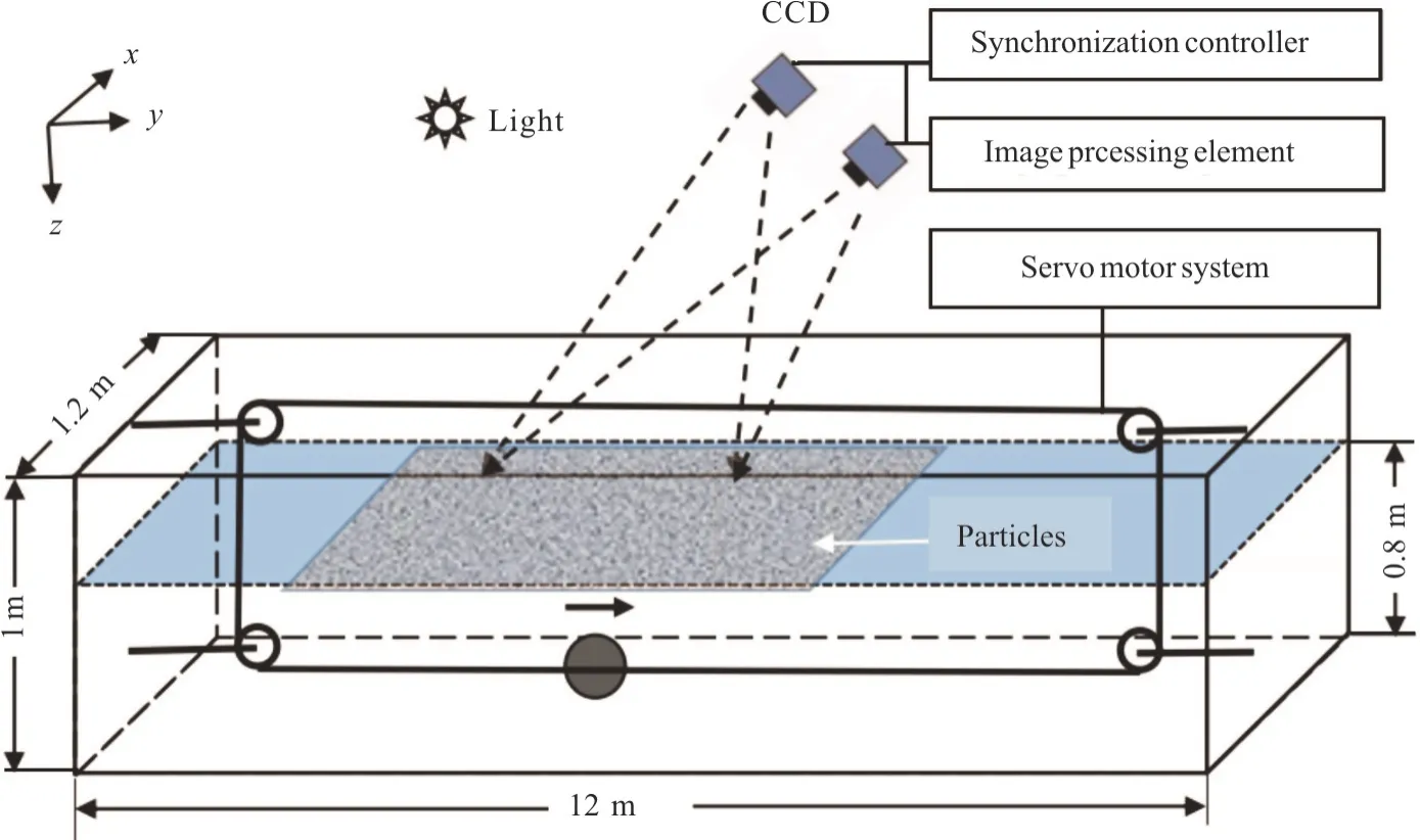
Fig.1 (Color online) Schematic diagram of experiment setup
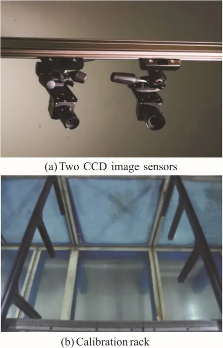
Fig.2 (Color online) 3-D surface measuring system
2.Measurement method
2.1 Fundamental principle
The optical methods for the surface measurements might be classified into three categories according to Gomit[3].The first class of methods is based on the use of a stereoscopic system and the image correlation; the second class of methods is based on the projection of a regular pattern,and the third class of methods is based on the absorption property of the light in a fluid absorption,namely,the refraction.In the present experiments,we measure the 3-D wave field on the water surface by using the first kind of techniques with a stereoscopic system and the image correlation to reconstruct the 3-D small- scale geometric structure of the surface wake induced by a moving submerged sphere.The image correlation calculation is based on the idea of the 2-D PIV technique with three components (2-D-3C PIV)[21].The 2-D-3C PIV technique is applied to measure the 3-D flow field in the interior of a fluid,where the velocity component in the third direction can be obtained by extracting the two 2-D velocity components in different directions of the flow field obtained by two- or multiple- image sensors according to their positional relationship.
The basic principle for the 2-D-3C PIV measurement is to determine the tracer particle’s locations in different images from two or more CCD sensors.Although the particle image information from a single sensor can only be employed to describe a 2-D velocity field,the 3-D spatial coordinates of the particle can be provided by matching the particle images of two sensors in different directions.Therefore,in the present experiments,the 3-D surface structure is reconstructed from the 2-D velocity information to obtain a single 3-D spatial coordinate.
We assume that a set of 2-D coordinates in a single image is a function of the 3-D spatial coordinates,expressed as

whereKis the coordinate vector in the image plane,Xis the spatial coordinate vector for the measured particle,andTis the transition matrix from the image plane to the spatial coordinate.In the measurement process,thei-th image sensor is calibrated first,i.e.,the conversion matrixTis determined according to the calibration parameters fromigroups,which are obtained by matching the 2-D image vectorKito the 3-D coordinatesXiof the preset particles.Then,the actualXcan be determined from the knownTand the experimentally measuredK.
As an example for the two image sensors,the procedure used for the 3-D reconstruction for the geometric structures of the wake on the surface is shown in Fig.3 as follows:
First,Tis determined from the 3-D spatial coordinates (x′,y′,z′) for the given calibration points and its 2-D coordinates (xa,ya) and (xb,yb)on the images of the two individual CCD sensors.Next,two 2-D-pixel coordinates of (x1,y1) and(x2,y2),mapping their characteristic particle in two respective images,can be obtained through a cross-correlation calculation such as the fast Fourier transform (FFT).Then,the three-dimensional spatial coordinates (x,y,z) for the actual particles can be reconstructed by the substitution of the related values into the transformation betweenKandX.
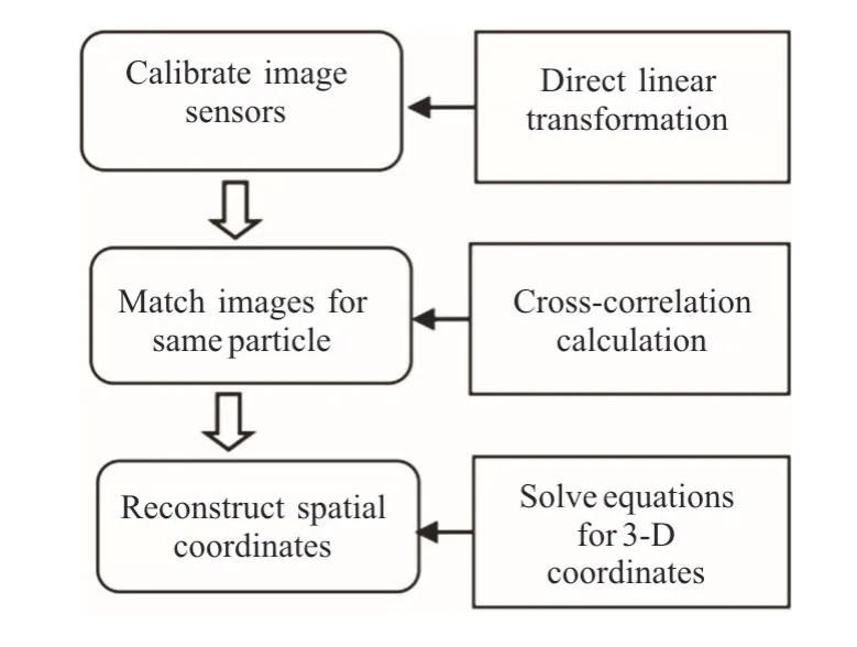
Fig.3 Flow chart of 3-D reconstruction
2.2 DLT calibration for particle images
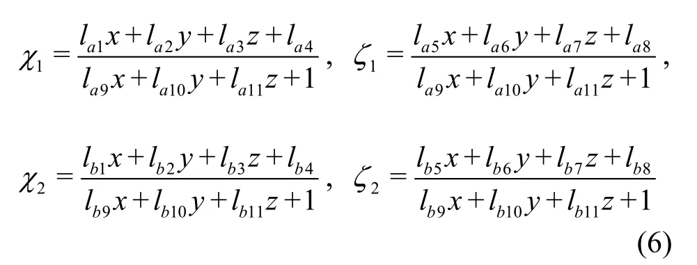
The direct linear transformation (DLT)[22],as a 3-D calibration method for a single image sensor,can be used for the high-precision calibration with multiple standard grid points,and its accuracy will increase with the increase of the number of grid points.Since the number of the regular grid points provided as a calibration reference for measuring the water surface in the tank is unrestricted,the DLT method is used to calibrate the measurement system in the present experiments.Let both the vectorsXandKbe (x,y,z) in the 3-D space and (χ,ζ) in the 2-D plane,respectively.Their functional relationship is expressed as

whereljis the calibration parameter and the subscriptj=1,2,… ,11 represents the number of selected parameters.By using the least squares method forljwe can find a set of equations for the known (x′,y′,z′) and (χ,ζ) that satisfy the matrix equation given by
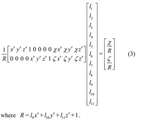
In general,one pair of equations for (χ,ζ) can be found from a reference grid point,so the eleven parameters are determined through at least six reference grid points for a single image sensor.Here,the least squares method is used to fit for the fifteen grid points in one image.In the calibration process,two cross bars separated by 0.50 m are used to suspend the vertical calibration rods,and three and two rods are suspended behind the left and right bars,respectively,so each pair of calibration rods at the cross bar is 0.25 m apart.A string of three reference points 0.05 m apart are determined for each vertical rod,as shown in Fig.4,and the vertical distance between each pair of points should be set much smaller than the horizontal distance to meet the high-precision measurement requirement for smallscale amplitudes.After the two image sensors are calibrated,the matrixTcan be determined.Then,the 3-D coordinateXof the particles can be calculated from the image plane coordinateKand the matrixT.
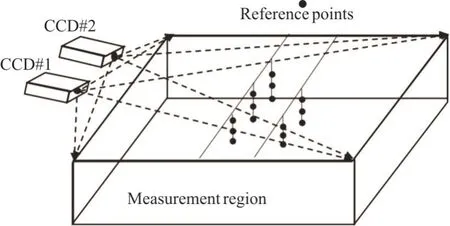
Fig.4 Diagram of the 3-D calibration system
2.3 Image matching for the same particle
Particle image matching refers to the process of finding the same particle in different images through the cross-correlation calculation,which can be carried out by two CCD sensors in different directions at the same time.The process adopted in the present method is different from the particle image matching in the conventional PIV measurements,based on the particle images at two adjacent moments.Enough tracer particles sprayed on the water surface are used to enhance the reflectivity of the free surface,so that the tiny deformation of the free surface can be easily observed through the CCD sensors.By means of the similar method,good results from the surface wave measurement were obtained[6].The fast Fourier transform is applied in the cross-correlation algorithm.Each suitable region in the two images at the same time is first selected as a query window so the 2-D coordinates of the same particle in different images can be determined by finding its peak in the window using the cross-correlation function.The two frames of image information can be written as the functionsf(α,β) andg(α,β),respectively,and their cross-correlation function is defined as

where Δαand Δβrepresent the spatial increments of the particles between two CCD sensors in the horizontal and vertical directions,respectively.Its discrete form is rewritten as

wheremandnare the vertical and horizontal pixel points in different query windows andMandNare their maximum values,respectively.Bothf(A,B) andg(A,B) are also known as the image functions in the query window,in which the variablesAandBrepresent the discrete values ofαandβ,respectively,and the magnitude ofRindicates the matching level betweenfandgfor these same particles.WhenRreaches the maximum value,the matched particle in the query window is discovered,and the corresponding image coordinate is recorded simultaneously.The FFT processing of the functionsfandgas well as the available size of the query window are used to improve the efficiency and the precision of the cross-correlation calculation.
2.4 Reconstruction of 3-D geometric coordinates
The 3-D coordinates of the image particle can be obtained from the image calibration of the two CCD sensors and from the two-frame matching images for these same particles.Let (x,y,z) be the actual spatial coordinates of the particle while its corresponding image coordinates are (χ1,ζ1) and (χ2,ζ2),respectively.These variables satisfy Eq.(6),where the subscriptsaandbin parameterslaiandlbirepresent two CCD image sensors,respectively.Therefore,the coordinate (x,y,z) can be determined by solving the above equations.
3.Results and discussions
3.1 2-D flow field on water surface
The flow field of the wake on the water surface by a moving submerged sphere can be measured by using the 2-D-PIV technique with a single CCD image sensor.Figure 5 shows the velocity distribution on the surface at a speed ofU=0.5 m/s and a depth ofh= 0.15 m .It can be seen that the typical Bernoulli hump on the surface is emerged near the top of the submerged sphere and that the Kelvin wake is far from the sphere.
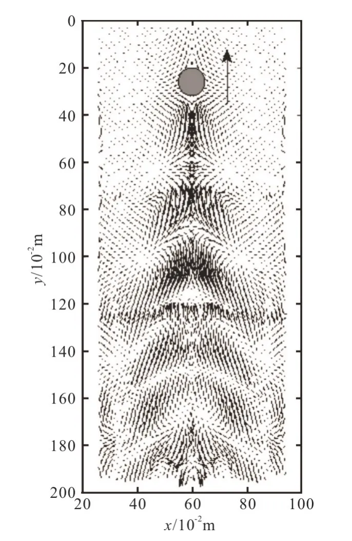
Fig.5 Typical flow field at the surface generated by a moving submerged sphere
The measured maximum velocity of the wake on the surface is approximately 0.05 m/s at the centre of the Bernoulli hump,only 1/10 of the model speed.A divergence field (called the source) can be found in front of the Bernoulli hump,as well as a convergence field (the sink) behind it,commonly described as the dipole model.In the flow field far from the sphere,the divergent flow is on the wave crest,while the convergence flow is on its trough.The former makes the water surface smoother,and the latter makes it rougher,as compared with the initial conditions,so the roughness of the surface is changed.It is well known that the sea-surface roughness is related to the backscattering cross-section in the marine microwave remote sensing,so the ship monitoring or the submarine detection can be achieved by determining the modulation of the wake flow owing to the sea-surface roughness.A highly accurate measurement of the wake structure in the laboratory will be helpful for interpreting the marine remote sensing images.
Our testing conditions and some results of the surface wakes for different values ofFrare shown in Table 1.It can be seen that the observed number of the Kelvin waves on the surface changes with the strong nonlinearity[23],the present results are consistent with those in cases ofFr<1 under the condition of weak nonlinearity.The parameter dz/his introduced to describe the non-dimensional vertical displacement on the water surface,and its variation withFris discussed in detail in the next section.speed of the small sphere and its submerged depth,increasingwith the increase of theFrvalue whenFr< 0.4 and remaining at the value of eight whenFr> 0.4.Because the trail half-angle for the Kelvin wake is determined in accordance with the outer edge of its multiple waves,the number of waves that can be observed in the measurement region must be sufficient to measure the angle.The measured magnitude of the tail half-angle remains approximately constant,close toφ= 19.47°,and very close to the theoretical value of the Kelvin wake in a homogeneous fluid with infinite depth.Despite those very dramatic changes of the wake in cases of large Froude numbers due to the
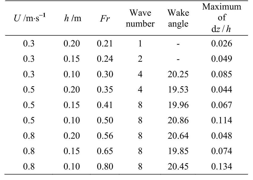
Table 1 Testing conditions and some results for wakes on surface
3.2 3-D geometric structure on the water surface
The 3-D geometric structure of the wake on the water surface can be obtained by the 3-D coordinate reconstruction using two CCD image sensors.The system errors in the experiment can be eliminated by subtracting the measured data from the background field on the rest water surface.The typical 3-D geometric structure of the wake on the surface at a submerged sphere depth ofh= 0.15 m and moving speeds ofU=0.3 m/s,0.5 m/s and 0.8 m/s is shown in Fig.6,in which the distinct Bernoulli hump appears on the water surface just above the submerged sphere and the particular field of the Kelvin wave is far from the sphere.The geometric structure of the wake on the surface for different values ofFrcan be analysed by changing the towing speed and the depth of the submerged sphere.At a small Froude number ofFr= 0.24,only the Bernoulli hump could be distinguished,but atFr=0.41,0.65,the displacements of both the Kelvin waves and the Bernoulli hump have a good symmetry about the centre axis and are decreased gradually along both sides,in which the Kelvin wake has obvious periodic characteristics in the direction parallel to the moving sphere.Here,a normalk-εturbulence model is used to test the above laboratory measurements,and almost the same numerical results are obtained,as shown in Fig.6,where the numerical geometrical conditions are completely consistent with the experimental conditions in the laboratory .Meanwhile,the measurement points along the centre axis on the surface are chosen for more finely testing the variations of the displacements for different values ofFr.
Figures 7,8 show the 2-D measurements for the wake-angle of the Kelvin waves both in the laboratory experiments and in numerical simulations,together with the time-series of the displacements on the surface for different values ofFr.It can be seen that both the amplitude and the wavelength of the Kelvin waves on the surface are increased with the increase of the value ofFr.By extracting the perturbations of the wake along the centre axis,quantitative results on the surface are obtained,showing that the measured maximum vertical displacement is 0.0134 m at the centre of the Bernoulli hump and that the minimum is approximately 0.0052 m at the far field of the Kelvin wake atFr= 0.65,whenFr<0.4,the maximum vertical displacement on the surface is always at the centre of the Bernoulli hump and is in the order ofO(1 0-3)m .The vertical displacements of both the Bernoulli hump and the Kelvin wave train are increased with the increase of the towing speed for the same depth,but they are decreased drastically in the field far from the sphere compared to the values in the vicinity of the sphere.The wavelengths of the Kelvin wave train are not changed significantly with the submerged depth of the sphere,but do increase greatly with the increase of the towing speed.In addition,the measured half-angle of the Kelvin wake obtained through its vertical displacements and the 2-D flow field on the water surface is almost consistent with the theoretical value,thus confirming that the angle is generated by the moving sphere only.
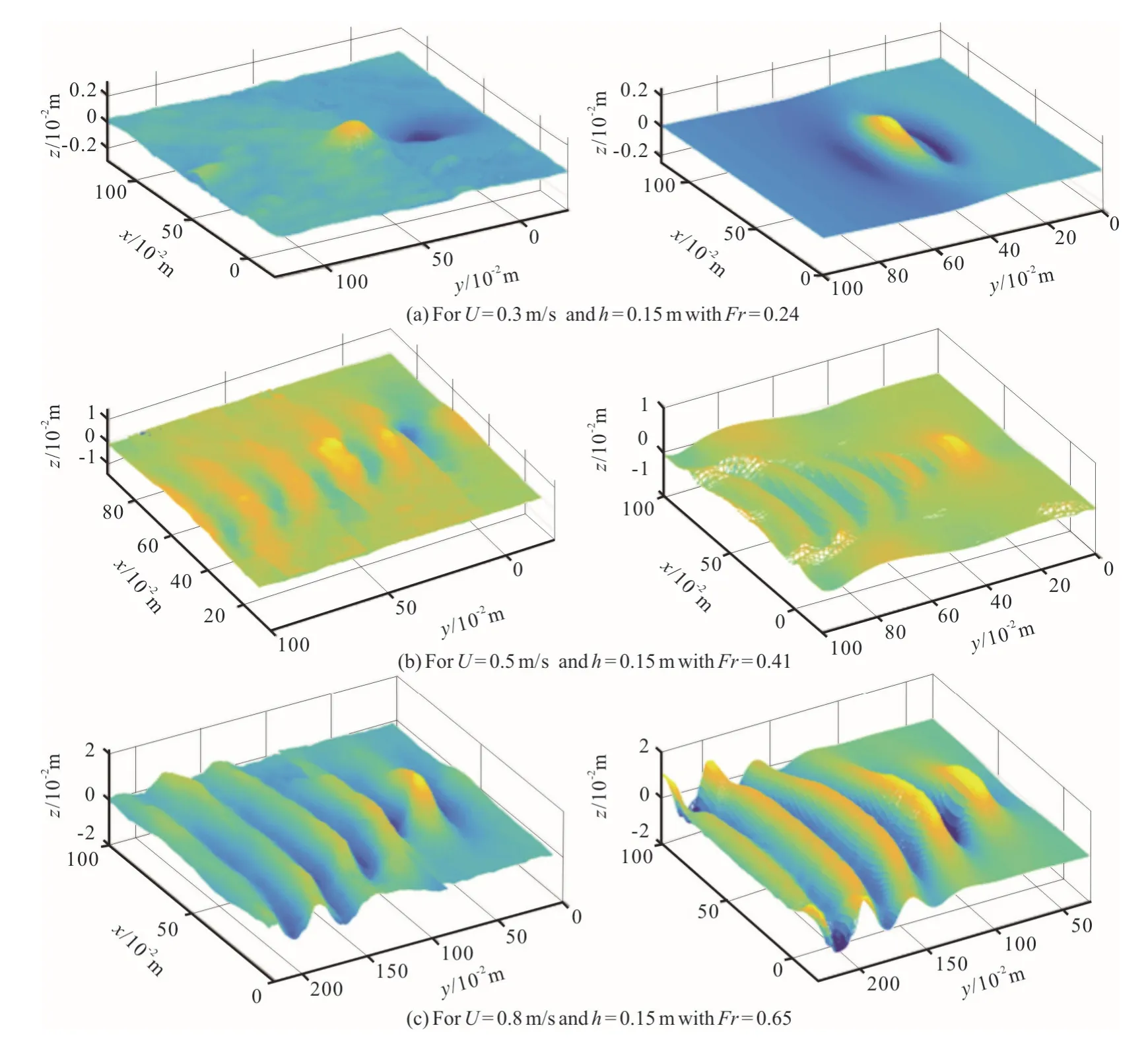
Fig.6 (Color online) Laboratory (left) and numerical (right) results for typical 3-D geometric structures of the wake on the water surface
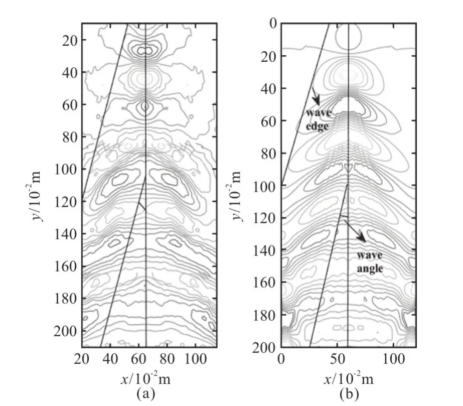
Fig.7 Comparison of simulation and experimental results for U =0.8 m/s ,h = 0.15 m with Fr=0.65
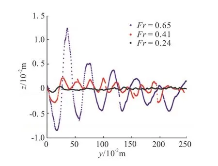
Fig.8 (Color online) Measuring surface displacements of the wakes for Fr=0.65,0.41 and 0.24
The geometric structure on the water surface could also be obtained by establishing the function of its vertical displacements with the 2-D grey levels in a linear array CCD image,which is called the direct optical method or the direct optical method (DOM)[8].The relative errors of the vertical displacements and the wake-angles obtained by the PIV and the DOM are listed in Table 2,where the displacements are relative to those obtained by the numerical method and the angles are relative to the theoretical value 19.47°.
The error analysis shows that the experimental results obtained by the stereo imaging technique have a higher precision than those obtained by the DOM:the average relative error of the displacements is approximately 11% against 23% for the DOM results.Here,the measurement precision is raised by at least a factor of two for the present stereo imaging technique relative to the direct optical method.The influence ofthe model movement on the water surface is diminished owing to the increase of its submergence depth,so the measurement errors are also decreased with the increase of the depth.In addition,the better robustness for the stereo imaging technique as compared with the DOM is verified from the smaller error fluctuation.
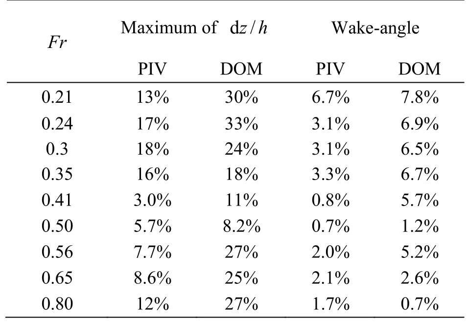
Table 2 Relative errors of vertical displacement and wakeangle
3.3 Error analysis and elimination
Because the 3-D reconstruction of a small-scale geometric perturbation on the surface in the present experiments is based on the stereo imaging principle,the main errors come from two aspects,as explained below.The first error source is the calibration method used for the particle images obtained by a single CCD sensor.The related errors of the measurements of the geometric displacements could be reduced by using a more accurate DLT calibration with a sufficient number of grid points.The second kind of error is generated by the image matching level for the same particles.This kind of error depends on the identification of the particles when processing the cross-correlation calculation between the sensor images,and its computational accuracy depends on the resolution of the images and the effective information.In fact,the requirement for the highprecision cross-correlation calculation is met because the image sensors used in our experiments have a resolution of 2 048×2 048 pixels and a focal length of 0.0125 m.
Now,for a small-scale geometric perturbation on the water surface,it is very important that its high-resolution vertical displacement and its 2-D velocity field can be obtained simultaneously in the stereo imaging technique.On the other hand,the direct optical method depends on the varying grey levels under the ambient light illumination,which commonly creates some uncertainty of the measured displacement increase.In fact,as shown in Table 2,the error of the stereo imaging technique relative to the numerical simulation is much less than that obtained using the direct optical method.The measured results for the maximum displacement on the surface under typical testing conditions demonstrate that the present method can improve the accuracy as compared with the direct optical measurements.
4.Conclusions
Based on the stereo imaging principle,an experimental measurement system for determining the 3-D small-scale geometric perturbation on the surface generated by a moving submerged sphere is built.First,the 2-D image coordinate of a moving particle is constructed by calibrating the double CCD image sensors and matching their images for the same particles.Then,the 3-D coordinates of the particle are identified by the transformation matrix of 2-D to 3-D spaces.Thus,the 3-D geometric reconstruction of the wake on surface was made.
The 3-D structure of the surface waves generated by a moving submerged sphere is measured successfully,and its small-scale vertical displacement is obtained accurately,with the measurement precision reachingO(1 0-4)m .The measuring accuracy in the present approach is improved by as much as 50%compared to the accuracy of the direct optical method.The experimental results show that both the vertical displacement of the wake on the surface and its induced velocity are increased with the increase of the value ofFr,with the maximum displacement at the Bernoulli hump core and a significant velocity field similar to the Kelvin wave train on the water surface.The 3-D geometric structure of the wake on the surface could be described by the measured half-angle of the train for different values ofFr,as consistent with the theoretical value of 19.47°.In addition,the present method can easily be applied to other measurements of small-scale perturbations on the water surface.
- 水動力學(xué)研究與進(jìn)展 B輯的其它文章
- Numerical simulation of condensation shock in partial cavitating flow on a hydrofoil*
- Flow regime and energy dissipation of SFS-type flip buckets*
- Spatial and spectral investigation of turbulent kinetic energy in cavitating flow generated by Clark-Y hydrofoil*
- A design of T-foil and trim tab for fast catamaran based on NSGA-II*
- Adaptive mesh refinement immersed boundary method for simulations of laminar flows past a moving thin elastic structure*
- Study of parametric roll in oblique waves using a three-dimensional hybrid panel method*

