Adaptive mesh refinement immersed boundary method for simulations of laminar flows past a moving thin elastic structure*
Mohammed Suleman Aldlemy,Mohammad Rasidi Rasani,A.K.Ariffin,T.M.Y.S.Tuan Ya
1.Centre for Integrated Design for Advanced Mechanical Systems,Faculty of Engineering and Built Environment,Universiti Kebangsaan Malaysia,43600 Bangi,Selangor,Malaysia
2.Department of Mechanical Engineering,College of Mechanical Engineering Technology,Benghazi,Libya
3.Department of Mechanical Engineering,Faculty of Engineering,Universiti Teknologi Petronas,31750 Tronoh,Perak,Malaysia
Abstract: One of the critical issues in numerical simulation of fluid-structure interaction problems is inaccuracy of the solutions,especially for flows past a stationary thin elastic structure where large deformations occur.High resolution is required to capture the flow characteristics near the fluid-structure interface to enhance accuracy of the solutions within proximity of the thin deformable body.Hence,in this work,an algorithm is developed to simulate fluid-structure interactions of moving deformable structures with very thin thicknesses.In this algorithm,adaptive mesh refinement (AMR) is integrated with immersed boundary finite element method (IBFEM) with two-stage pressure-velocity corrections.Despite successive interpolation of the flow field by IBM,the governing equations were solved using a fixed structured mesh,which significantly reduces the computational time associated with mesh reconstruction.The cut-cell IBM is used to predict the body forces while FEM is used to predict deformation of the thin elastic structure in order to integrate the motions of the fluid and solid at the interface.AMR is used to discretize the governing equations and obtain solutions that efficiently capture the thin boundary layer at the fluid-solid interface.The AMR-IBFEM algorithm is first verified by comparing the drag coefficient,lift coefficient,and Strouhal number for a benchmark case (laminar flow past a circular cylinder at Re=100) and the results showed good agreement with those of other researchers.The algorithm is then used to simulate 2-D laminar flows past stationary and moving thin structures positioned perpendicular to the freestream direction.The results also showed good agreement with those obtained from the arbitrary Lagrangian-Eulerian (ALE) algorithm for elastic thin boundaries.It is concluded that the AMR-IBFEM algorithm is capable of predicting the characteristics of laminar flow past an elastic structure with acceptable accuracy (error of ~0.02%) with only ~1% of the computational time for simulations with full mesh refinement.
Key words: Immersed boundary method,finite element method,adaptive mesh refinement,two-stage velocity-pressure correction,thin deformable structures
Introduction
Fluid-structure interaction takes place when the structure deforms due to the fluid flow.Fluid-structure interaction between viscous flows and thin deformable bodies is one of the intriguing problems in fluid mechanics because of their relevance to realworld phenomena such as the effects of hemodynamic factors in blood vessels[1-2]and blood flow interaction with elastic veins.Immersed boundary method (IBM)is one of the effective methods used to solve fluid-structure interaction problems.IBM was initially developed by Peskin to simulate blood flow through the heart valve[3-5].In Peskin’s approach,the heart valve is modelled as a thin,viscoelastic structure with time-dependent elastic parameters[6-7].
A number of studies are presented by previous reviews for IBM.That are categorized into two main families: the continuous (or diffuse) and discrete (or sharp) methods.The diffused interface schemes via classical IB methods[4,8],direct forcing methods[9-10],and penalization methods[11-13]exist as well as for sharp interface schemes such as cut-cell methods[13-15].In the IBM cut-cell methods[14-16],the governing equations are not modified,and only the computational cells at the IB are altered to formally define finite-volume or finite-difference operators.These methods are accurate,satisfy the pressure decoupling constraint and are able to handle a very thin interface.However,their complexity and slow convergence due to the small-cell problem are key disadvantages of these methods.Kajishima et al.[17]proposed an extremely simple IBM to simulate particle-laden flows.Similar to the direct-forcing IBM,the body force is evaluated directly at the immersed boundary based on the velocity of the solid domain.The fluid and solid velocities are smoothly interpolated by using a solid volume fraction at the boundary cells.Different from the works of Breugem[18],Di and Ge[19]and Kempe and Frohlich[20-21],the velocity is explicitly set to that of the solid body inside the solid cells at the end of the time step.However,Kajishima’s cut-cell approach does not fulfil the divergence-free condition within vicinity of the fluid-solid interfaces[9,22].The cut-cell approach is now jointly applied with the level-set method to facilitate the tracking of the immersed boundaries[13,23-24].Since higher accuracy and conservation properties are attainable near the interface,the cut-cell method is suitable for numerical analyses of FSI with turbulent flows,despite the rarity.This is one advantage of the cut-cell method.However,a major drawback for this method is the difficulties involved when considering 3-D problems with complex geometries.Most applications of the cut-cell method were focused on 2-D problems[15,25-27].This is a result of the inherent difficulty encountered when applying cut-cell method to 3-D problems since cut-cells can mimic a variety of possible geometric shapes.This possibility becomes a disadvantage when dealing with the arbitrary geometry which is already complex as it may be with typical real-life applications.The application of the cut-cell method was recently performed by Chen and Botella[23]for numerical FSI problems with 3-D flows[28].
Most IB methods are not appropriate approaches for thin sharp-interface object FSI problems,which require an accurate representation of the quantities at the interface,since the methods do not deliver accurate and sharp representations of the stress jumps over the thin fluid-structure interface.Furthermore,for IB methods exist some mesh-size dependencies between fluid and structure to achieve an accurate kinematic matching between them.Moreover,since the interaction between fluid and structure fields is a volumetric coupling,the structure is affected by an artificial viscosity or it is forced to be incompressible.
In IBM,a fine mesh is required for discretization using Eulerian mesh for flows within proximity of the immersed boundary.However,such a high mesh resolution is not required for regions farther away from the immersed boundary and therefore,it is impractical to use fine mesh for the entire computational domain because of the high computational cost.Hence,it is more practical to implement adaptive mesh refinement (AMR),which involves generating a fine grid in regions where high spatial resolution is most critical while a relatively coarse resolution is used for other regions in the computational domain where it is expected that there are no large gradients in the flow characteristics.AMR makes it possible to make effective use of computational resources compared with non-adaptive schemes.However,it is crucial to ensure careful design and implementation of the data structure[29].
Hartmann et al.[30]used an adaptive hierarchically structured mesh for IBM to introduce local spatial refinement in the Eulerian mesh near the immersed elastic interfaces.Griffith[31]found that the results generated by the IBM with adaptive mesh were comparable to those obtained using IBM with fixed mesh of the highest resolution.Roma et al.[32]found that the results obtained from adaptive mesh did not differ significantly from those obtained using a fixed uniform Cartesian mesh even though a high spatial resolution was only used within proximity of the elastic boundary.
Several scholars have made significant progress in this field in recent years.According to Sotiropoulos and Yang[28],the main limitation of the IBM is that the lattice nodes in the neighbourhood of the solid boundary cannot be selectively clustered,which increases the complexity of the simulations of turbulent flows at high Reynolds numbers.They highlighted that future studies should be focused on multi-resolution simulations to address this issue,in which IBM is integrated with AMR.Such advancements will significantly increase the simulation capabilities of current IBMs,which will greatly facilitate in solving real-world problems pertaining to fluid-structure interactions[22].Indeed,modelling the interactions between fluid flow and deformable solid is particularly challenging due to the combination of two phases of materials[33-34].
Recently,Posa et al.[35]developed a structured algorithm for iso-parametric mapping,which simplifies local refinement near the Lagrangian mesh of an immersed body.The refinement level was tied to the local Eulerian mesh of the fluid flow,which may vary in space and time.The method was considered to be efficient because only a small memory capacity was required to save the data.In addition to the nodes and connectivity data of the triangulation,only a small size of memory was equipped with markers per surface element for reconstruction when required[35].
Efforts have also been made to develop different IBMs.According to Kajishima and Takeuchi[22],it is crucial to develop IBMs that are able to capture the characteristics of flows through narrow passages or flows around very thin objects.They also highlighted issues concerning fluid-structure interactions in multiphase flows.New techniques need to be developed to overcome the drawbacks of existing IBMs,which will simplify the computational process and increase the accuracy of the numerical solutions.
Hence,the present study intends to show a new series of additions in fluid-structure interaction utilizing IBM for thin bodies.AMR is integrated with cut-cell immersed boundary finite element method(IBFEM) and two-stage pressure-velocity correction in order to improve the accuracy of the solutions near the fluid-structure interface for rigid and elastic thin bodies.Kajishima’s cut-cell IBM is effective in treating the boundaries and therefore,this method is adopted in this work.Simulations of fluid-structure interaction problems using IBMs generally require high spatial resolution,which can be computationally expensive.To address this issue,AMR is used to achieve high spatial resolution within a small region of the flow around the immersed boundaries,which will greatly simplify the computations and reduce computational cost.The AMR provides special treatment for momentum exchange for any arbitrarily shaped thin structures.
The algorithm was developed by adding a layer of deformable fluid nodes near the immersed boundary of the thin solid.It is imperative to implement a suitable mesh size for the boundary layer in order to accurately capture the flow characteristics at the fluid-structure interface without incurring significant computational cost.
In order to demonstrate the applicability of the AMR-IBFEM algorithm,a simplified model is developed,consisting of a two-dimensional thin elastic structure (beam) immersed in viscous,incompressible fluid.The AMR-IBFEM algorithm is written in FORTRAN language on Ubuntu 16.04 LTS operating system and it can easily capture the pressure discontinuities across the interfaces which coincide with the thin elastic structure while reducing the computational time.The problem under consideration retains the important physical features such as large deformations which are common to more complex models.
1.Numerical method
This work is focused on a dynamic system,which involves interactions between viscous incompressible fluid flow and the moving boundaries of a thin structure.Hence,the governing equations of fluid dynamics and numerical method will be described based on the interactions of the moving boundaries of the thin structure.It is assumed that the fluid (gas or liquid) is incompressible and Newtonian.The finite difference approach is used to model the fluid flow,where a rectangular grid is used in the Cartesian coordinate system.
1.1 Governing equations of fluid dynamics
The Navier-Stokes equations are used to describe the fluid dynamics for the fluid-structure interaction problem in this study,as follows:

whereufis the fluid velocity,pis the pressure,ρfis the fluid density andvfis the kinematic viscosity of the fluid.The Eulerian variables are arranged using the Cartesian mesh.Equations (1) and(2) are determined based on the second-order finite difference scheme in space and time.Following this,Kajishima’s cut-cell IBM is used to address the momentum exchange at the fluid-structure interface,as described in the following section.
1.2 Cut-cell immersed boundary method
One of the challenges in fluid-structure interaction problems is to accurately predict the flow characteristics and corresponding forces,which requires previous knowledge of the moving structures.In IBM,the no-slip boundary condition is enforced by adding a forcing term to the governing equations.This forcing term is related to the difference between the velocity of the moving structure and fluid flow velocity at the boundary.Strong coupling is adopted in this work,in which the fluid and structure are viewed as nodes derived from a dynamic system.This is done by embedding all of the governing equations iteratively and concurrently.In fact,IBM addresses the momentumexchange during fluid-solid interactions at the cell level,where each cell is partially occupied by solid particles[36-37].In this work,a velocity field is introduced at the fluid-solid interface,where the cells are partially filled with solid particles and solved using the IBM.The velocity field is introduced by averaging the volume of the local fluid velocity (uf) and solid velocity (up) in each cell.The velocity field is given by

whereα(0 ≤α≤ 1) denotes the volume fraction of the solid particles within a cell,as shown in Fig.1.Next,the solid particle velocity (up) is decomposed to translate and rotate the elements such thatup=vt+r×ωp,wherevtrepresents the velocity of the object,ωpis the angular velocity andris the relative location from the centre of gravity to a particular point within an integral area.
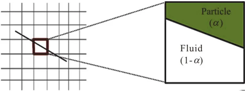
Fig 1 (Color online) Concept of the cut-cell IBM,where each Cartesian cell is partially occupied by fluid and solid particles
To apply immersed boundary method,a suitable and efficient surface digitizer is required.This is due to the requirement that each solid volumetric fraction is needed to be evaluated at each cell.The simplified and improved digitizer also enable it for use of arbitrarily shaped objects.It is based on the following hyperbolic-tangent function to digitize the fluid solid interface for obtainingα.The hyperbolic tangent function is used to determine the volume fraction,which is given by:
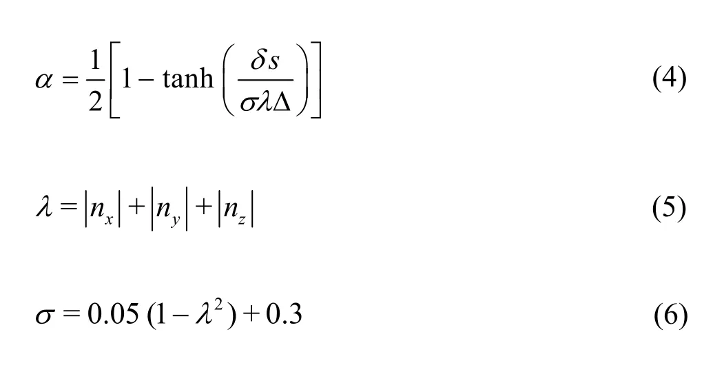
wheren= (nx,ny,nz) represents the normal outward unit vector at the element surface whileδsdenotes the distance between the centre of the element and its surface.This formulation,which was developed by[38],is known as the surface digitizer.This digitizer was proven to be accurate when the surface digitizer was used to evaluate the particle volume with 20 and 16 cells covering the diameter of spherical particle,Eq.(6) gives 0.26% and 0.43% in error respectively.Also from the simplified formulation,the digitizer was able to reduce the processing time by 25% compared with the original digitizer.Thus,the fluid-solid interaction at the boundary was determined by integrating the velocity field based on the Navier-Stokes equations:

The scheme used to determine the time advancement foruis given by:
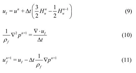
where the superscripts refer to the time step,Δtis the time increment,uIis the intermediate velocity.The time advancement in a single continuum is computed by using the second-order Adams-Bashforth method and the fractional step method.The Poisson equation is solved by employing the divergence of the intermediate velocity (uI),which serves as a source term for the pressure (pn+1).The intermediate velocity is then corrected and the time-step velocityis integrated.
1.3 Two-stage pressure-velocity correction
The first challenge in using conventional IBM to solve fluid-structure interaction problems is that this method may lead to fluctuations in the computed pressure,particularly for thin structures.Even though these fluctuations are considered to be the inherent features of IBM,they can be significantly reduced by applying a second correction step for pressure.This approach is a significant improvement for simulations of flows around thin structures where it is particularly challenging to compute the flow characteristics at the thin interface.The velocity field of the fluid cells occupied by a solid region is subjected to an interaction force,given by Eq.(3).However,careful treatment is needed to derive the pressure field affected by this change.Because the pressure field was corrected by the enforcement of an interaction force,the second derivative of pressure is used for the a affected cells.A small domain surrounding the region close to the object is chosen for the correction.To demonstrate this scheme,the velocity fieldu(Eq.(3)) is defined asThe simplifid marker and cell method is used to determine the scalar values for the velocity and pressure correctionIn this case,the projection method is used to correct the pressure field near the surface of the structure[39]:
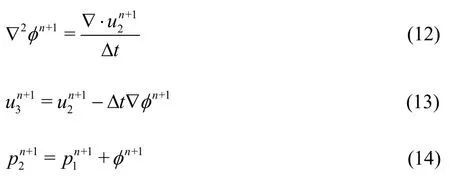
The second challenge involves integrating the IBM with FEM in order to solve fluid-structure interaction problems between fluid flow and a thin elastic structure.The challenge lies in how to incorporate elastic effects into fluid dynamics.At present,there are many approaches to address this problem,including the complete Euler method[40].In the IBFEM approach,the immersed solid force interacts with the solid internal force field by superposition of the interaction forces using the FEM scheme.This approach retains the computational cost without compromising the accuracy of the results.The thin elastic structure is represented by a group of nodes in a 2-D domain.
1.4 Finite element method
FEM is used as a solver for the thin elastic structure.The equations of motion at each node of the arbitrary-shaped structure are computed using the FEM algorithm.A homogeneous isotropic elastic material is selected as the material of the thin structure under plane strain condition.The no-damping displacements for each node of the solid are inserted into the Navier-Stokes equations in order to update the fluid flow solver,as follows:
The governing equations are discretized at each cell using the method of weighted residuals and the same method is used to obtain the results in the form of the following linear matrix

whereρ,t,ui,xj,σijFiand represent the density,time,displacement,coordinate,and additional forces,respectively.zthe global displacement column is vector andKis the global stiffness matrix.The Wilson-θscheme is used for the transient time step simulations.Wilson-θis an implicit method for solving equations or systems of equations,such as the second-order equations of motion (16),in a step-by-step manner.Wilson-θwas originally developed to overcome stiffness problems in finite element analysis.The volume force tensorFin the volume element domainVeare added to the surface force tensortat the boundary element domainΩbto represent the external forces.The volume force tensor is given by

where dΩrefers to the boundary elements andNrepresents the shape function.In this work,only one method is usedtapply the fluid forces.This is done by explicitly computing the fluid pressure and viscous forces and applying them as the surface forces

The fluid pressure links the fluid,deformable structurepin Eq.(14),and viscous forces,to the surface forces {t} in Eq.(18),as follows

where {nx,ny}Tis a normal outward vector at the boundaryΩThe bending element is composed of two nodes where each node has freedom degrees.The bending element is transformed along the global axes.
2.Adaptive mesh refinement
In the AMR concept,are ctangular grid is developed byappropriatelynestingtheentirecomputational do main w ithin sub-blocks while ensuring an acceptabledegreeoferrorandminimumcomputational time.The time step is modified according to the level of mesh refinement.The time step for mesh refinement can be expressed mathematically as Δt= ΔT/2N,whereN= 1,… ,plevandplevis the number of patches correlated to the cell size.The time step is calculated in advance for the solution at any mesh refinement level and therefore,a procedure is developed to synchronize the solution levels.The sub-blocks of the mesh are introduced from the boundaries of the largest cell grid,as shown in Fig.2.This is the AMR concept for a single layer.The original background mesh and the boundaries of the mesh for grid 1 are used as the intermediate starting points.The mesh for grid 2 is defined by the fluid motion.The mesh refinement with finer resolution is achieved by creating a rectangular grid from the boundaries of grid 2.
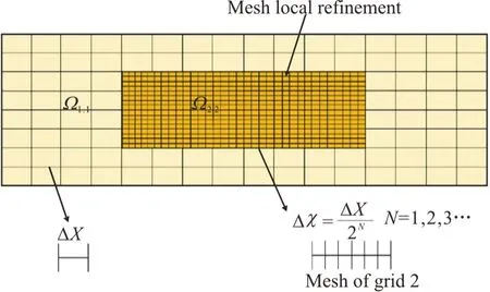
Fig.2 (Color online) AMR for a single layer in a 2-D domain
The AMR scheme is used to discretize the computational domain,where the nodes are interpolated to create new ones.This is done by computing the stationary flow in the very thin mesh refinement layer.The nodes at intervals ΔX=0.01 are used to build the preliminary fluid mesh and the final mesh size consists of 9 600 nodes spaced at an interval of Δx= 0.00125 .One level of refinement meansthattheresolutionisincreased for each step at the indirect boundary.The accuracy of the fixed mesh can be enhanced by applying AMR with the finest resolution around the thin object.However,it is worth noting that even though AMR enhances the accuracy estimating the motion of the structure.Due to the transient instability (especially for the motion of large objects),the mesh may need to be frequently updated in order to adhere to the implicit interface.In this case,it is more beneficial to create a layer of small-sized cells along the surface of the thin object to ensure the mesh size is optimal at the boundary layer.
AMR is implemented in this code,where the mesh resolution of the solid is different from that for the fluid.The locations of nodes for the solid are defined for each time step in order to create the refined mesh.Next,the fluid nodes within vicinity of each solid node are detected.The fluid nodes adjacent to each solid node are categorized and interpolation is then carried out on the categorized fluid nodes.The meshing process is renewed using the newly created nodes,generating the refined mesh.A parameter is introduced to control the degree of interpolation in the FORTRAN program.Once the fluid-solid interaction is accomplished using the FORTRAN code,the refined mesh returns to its original coarse size.The simulation is then iterated at a new time step and the whole process is repeated again.Table 1 shows the partitioned AMR-IBFEM algorithm used to coarsen and refine the mesh for a single time step.The algorithm shows AMR-IBFEM algorithm developed in this work to obtain the solutionunat timetnup to solutionun+1at timetn+Δt.
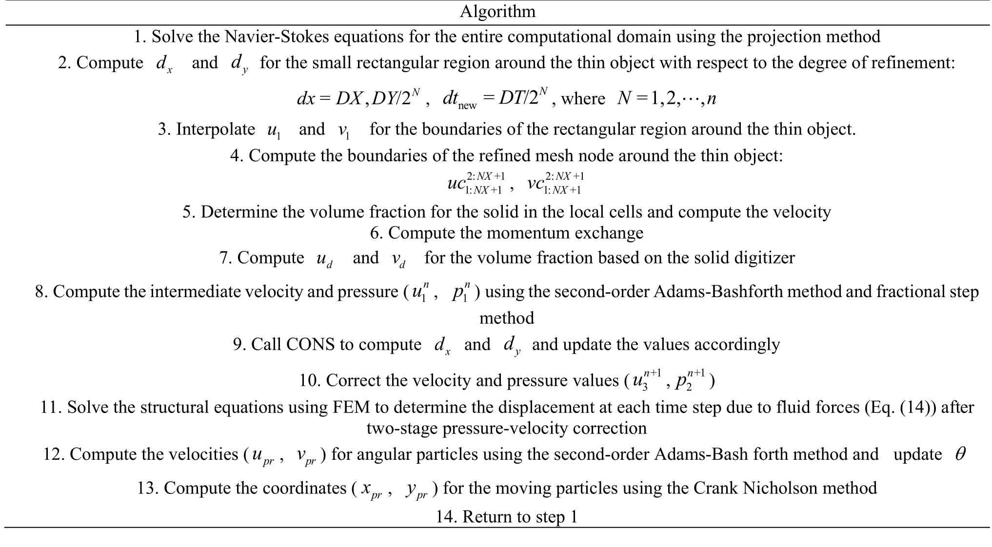
Table 1 shows the AMR-IBFEM algorithm for mesh refinement of a fluid-solid interaction system with one time step
2.1 Interpolation on the adapted mesh and boundary layer
The interpolation of data from a coarse grid block to a finer grid block is an essential step to perform computations on a hierarchy of meshes.It is necessary to interpolate all of the nodes from the old mesh to the new one due to the time variability.Hence,a linear interpolation approach is used for this purpose,as shown in Fig.3.First,an initial nodeNoldis located in the Cartesian mesh and then,a new nodeNnewis generated for the new mesh.Here,the quantities atNneware obtained from the local representation forNold.The level set function is used in the continuous space as an advanced step in the interpolation procedure.The nodeNoldis located using a specific procedure.The primary nodeN1newis located based on a 1-D search in relation toN1old,where the search direction is attained using the steep descent algorithm.This is followed by the interpolation of the second nodeN2newthat is boarding ontoN1newwhile searching for the correspondingN2old.This process is repeated until all of the new nodes are located on the old mesh.The computational cost of the search algorithm varies linearly withN,which represents the number of nodes on the new mesh.
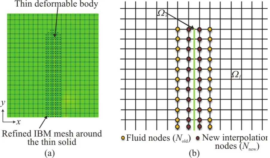
Fig.3 (Color online) Eulerian and Lagrangian meshes,where sΩ and Ωf denote the solid and fluid regions,respectively
The velocity and pressure are also interpolated using the interpolation procedure above,generating new velocity and pressure values.Since the positions of the solid nodes change in every step,the interpolation process needs to be implemented for each time step.Simulations of the thin structure are carried out using FEM and the fluid-solid interaction is computed in each time step.The pressure within vicinity of the solid surface is first computed and this pressure is used to determine the force to be exerted on the solid.In another solver,the force computed from the previous step is used in the FEM simulation to compute the displacement of the solid.Once the new locations of the solid nodes are defined,the nodes are used in the next step to determine the new velocity and pressure nodes.
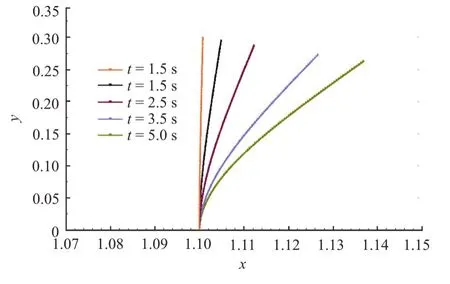
Fig.4 (Color online) Deformation pattern of the thin elastic structure immersed in uniform laminar flow
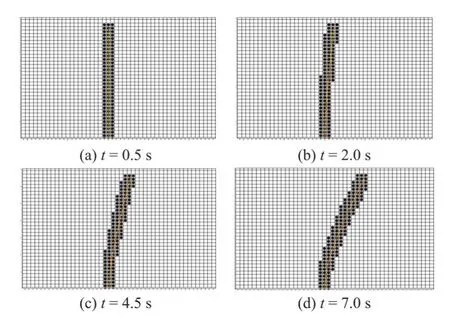
Fig.5 (Color online) Snapshots of the deformed thin elastic structure at different time steps.Note that a fixed mesh is used for the fluid flow (indicated by the white cells)whereas an adaptive mesh is used within proximity of the thin elastic structure (indicated by the black cells) to capture the physics of fluid-solid interaction
2.2 Zonal mesh refinement for large deformation of elastic thin structure
A thin elastic structure representative of a membrane valve with lengthL,widthb,and very thin thicknesshis placed perpendicular to the laminar freestream direction,as shown in Fig.4.The base end of the thin valve is fixed while the top end is moveable.The thin elastic structure is positioned at the centre of the computational domain.Figure 4 shows the deformation pattern of the structure with respect to the simulation time.The simulations are carried out using structured mesh with a mesh size of 220×41,where most of the nodes are clustered within proximity of the thin immersed boundary.Figure 5 shows the variation of the refined mesh around the thin elastic structure at different time steps and it can be seen that the structure deforms due to fluid forces as the flow develops and the AMR-IBFEM algorithm adapts th e mesh refinement in accordance with the deformation of the solid.The locally refined mesh surrounding the object is indicated by the black-coloured cells in Fig.5.The advantage of the AMR-IBFEM algorithm is evident from the results,where the locally refined mesh surrounding the object changes dynamically corresponding to the solid deformation.With this algorithm,the computational cost can be significantly reduced because the meshis refined an d adapted within a small region where flow gradients are critical rather than the whole computational domain.There are ~9 600 nodes in the refined mesh, where Δx= Δy= 1.25× 1 0-3and Δt=6.25× 10⁻⁶s.
3.Simulation set-up
The settings used for simulations of 2-D laminar flow past a thin elastic structure are described in this section.The computational domain has the following dimensions: length×height=2.20 m×0.41 m.The thin elastic structure is positioned at the centre of the domain at an axial distance of 1.10 m from the inlet.The height of the thin elastic structure is 0.30 m and the structure is composed of 200 nodes.The Poisson ratio,Young’s modulus,and density of the thin elastic structure are set as 0.3 MPa,5.0 MPa and 1.0 kg/m3,respectively.Figure 6 shows the geometry of the solution domain while Table 2 shows the parameters used for the fluid flow.
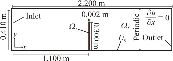
Fig.6 (Color online) Computational domain and boundary conditions for the 2-D thin elastic structure
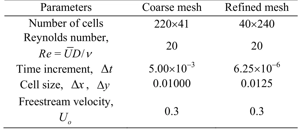
Table 2 Parameters used for the fluid flow in the 2-D computational domain
The first step of the numerical procedure involves computing the fluid characteristics using an Eulerian mesh.The total pressure force acting on the thin structure is then used as the input for the structural simulations using FEM in order to obtain the velocity and displacement of the solid.The new location of the object is then traced in Lagrangian fashion and the appropriate virtual forces are formulated at the interface locations,which are then transferred seamlessly onto the nodes of the Eulerian mesh using IBM.The solutions are then advanced to the next time step.The most convenient way to transfer data between the IBM and FEM meshes is to ensure that the nodes are coincident.The pressure force,velocity,and displacement need to be interpolated to the nearest node if the nodes are not coincident.The Reynolds number is also supplied to the IBM code to compute the laminar scales of the flow.One of the main challenges in using IBMs is to achieve a high resolution at the immersed boundary,particularly for thin structures.In this work,the thickness of the elastic structure (representative of a membrane valve) is considered to be ultra-thin(thickness: 0.1 mm-1.0 mm),and the high resolution is achieved by successive linear interpolation from the coarse grid block to fine grid block using the AMR-IBFEM algorithm.The number of nodes at the boundary of the thin elastic structure is crucial to obtain reliable results.
4.Results and discussion
The robustness and accuracy of the AMRIBFEM algorithm in simulating 2-D incompressible viscous flows around elastic a thin structure were assessed and the results are presented and discussed in this section.It is worth revisiting the objective of this study at this point,which is to develop an AMR technique that is suitable for stationary and moving thin elastic structure.The AMR technique must be capable of handling the interactions of deformable compressible/incompressible structures subject to severe deformation in incompressible flows and more importantly,the AMR technique must be capable of resolving the flow physics in the boundary layer adjacent to the surface of the thin object.
The AMR-IBFEM algorithm developed in this study is able to address the deformations of thin structure in a cost-effective manner and provide high resolutions near the boundaries of the elastic thin structure throughout the simulations,rendering the proposed model suitable to simulate real-world FSI problems.In the AMR-IBFEM model,mesh layers(each with different cell sizes) are generated in the boundary layer where large flow gradients exist such as flow separation and flow re-attachment.Different algorithms were used to simulate three cases in order to demonstrate the capability of the AMR-IBFEM model: (1) Flow past a stationary circular cylinder(IBM with mesh refinement),(2) Flow past a stationary thin structure (AMR-IBM) and (3) Flow past a moving thin elastic structure (AMR-IBFEM).
4.1 Laminar flow past a stationary circular cylinder at Re=100
The AMR-IBFEM algorithm is first verified using a benchmark case[41]for laminar flow past a stationary circular cylinder.The length and height of the computational domain are 220 m and 0.41 m,respectively,and the circular cylinder has a diameter of 0.1 m.The coordinates of the cylinder are (xc(t= 0),0.22) prior to the simulations.The Reynolds number is defined by,whereis the mean flow velocity,Dis the characteristic length(i.e.,diameter of the cylinder),andνis the kinematic viscosity of the flow.The Reynolds number for the benchmark case is 100.The kinematic viscosity and density of the fluid are set to 0.001 m2/s and 1.0 kg/m3,respectively.

Table 3 Comparison of the drag coefficients,lift coefficients,and Strouhal numbers obtained from the AMR-IBM algorithm and those from the published literature and OpenFOAM at Re=100

Fig.7 (Color online) Velocity contour for laminar flow past a stationary circular cylinder obtained using the AMR-IBM
The hydrodynamic force characteristics of the cylinder are evaluated in terms of the non-dimensional drag and lift coefficients,which are defined byandrespectively.The Strouhal number (St) is used to characterize the oscillating flow and it is given bySt =Df/,whereDis the characteristic length (i.e.,diameter of the cylinder),fis the vortex shedding frequency,andis the mean flow velocity.TheCD,CLandStvalues obtained by the AMR-IBFEM algorithm for the benchmark case are compared with those obtained by[41-42],and Open FOAM open source computational fluid dynamics software,as shown in Table 3.In general,there is very good agreement between the results obtained from the new algorithm and those of other researchers[41-42],where the differences in the values are well within a margin of error of 1.5%.This indicates the reliability of AMR-IBM algorithm in simulating laminar flows past a simple structure in the 2-D domain.The left,bottom,and top boundaries of the fluid flow domain are set at zero velocity.Hence,the flow is fixed and bound to the movement of the cylinder.Figure 7 shows the velocity contour for laminar flow past a stationary circular cylinder obtained using the AMR-IBM algorithm,with refined mesh near the boundary of the structure.
4.2 Laminar flow past a stationary thin structure
Once the AMR-IBM algorithm has been verified,the algorithm is used to simulate laminar flow past a stationary thin structure.The simulation set-up is shown in Fig.8.In this test case,the fluid forces cause the thin structure to deform and the refined mesh within proximity of the boundaries is adapted to capture the physics of the fluid-solid interaction.
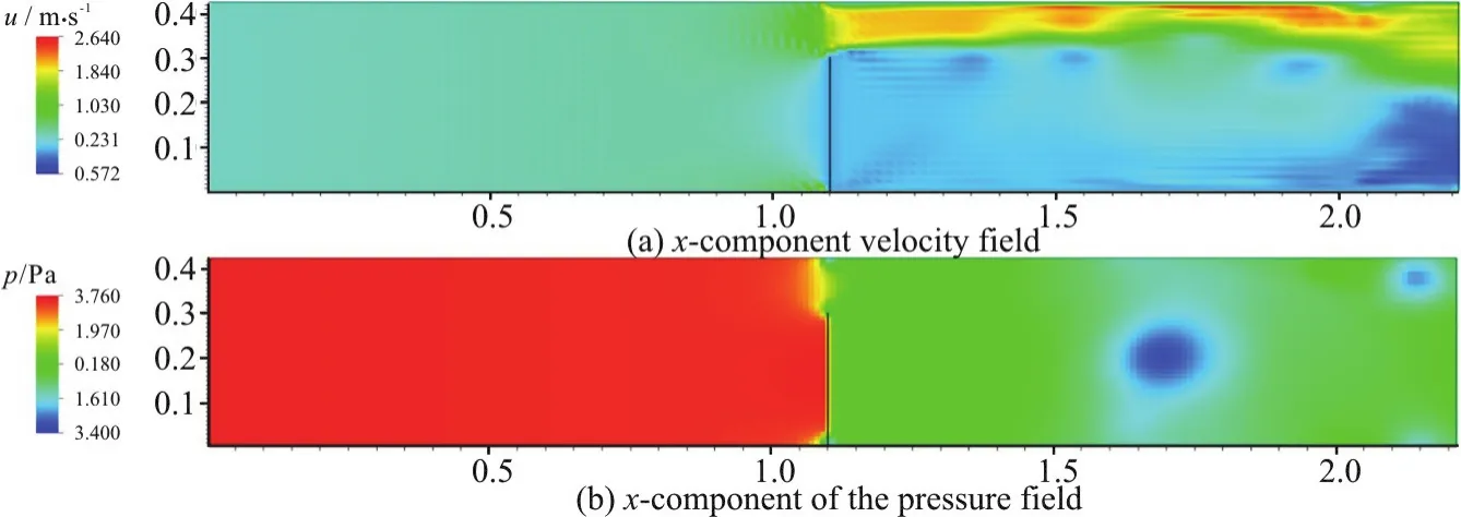
Fig.8 (Color online) (a) Velocity contour and (b) pressure contour of flow around a stationary thin rigid structure with very fine mesh around the object
Figures 8(a) and 8(b) show the velocity and pressure contours of the laminar flow past a stationary thin structure.It can be seen that the flow velocity is generally higher above the structure,beginning from the mid-point of the structure,as indicated by the yellow,orange,and red regions.Interestingly,the flow slows down immediately before the object and the flow velocity remains low behind the object,as indicated by the regions marked in blue in Fig.8(a).The pressure is significantly higher before the thin structure,as indicated by the red region,and the pressure drops abruptly after the flow passes by the object.
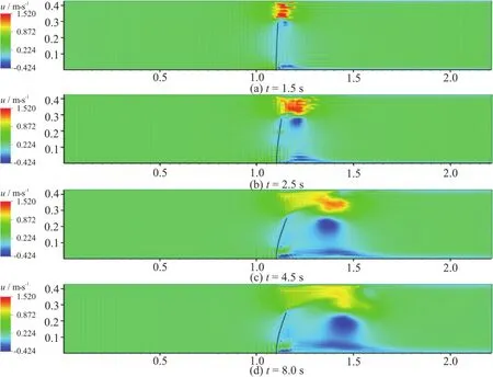
Fig.9 (Color online) Velocity contours of the deformed thin elastic structure obtained using the AMR-IBFEM algorithm at different time steps
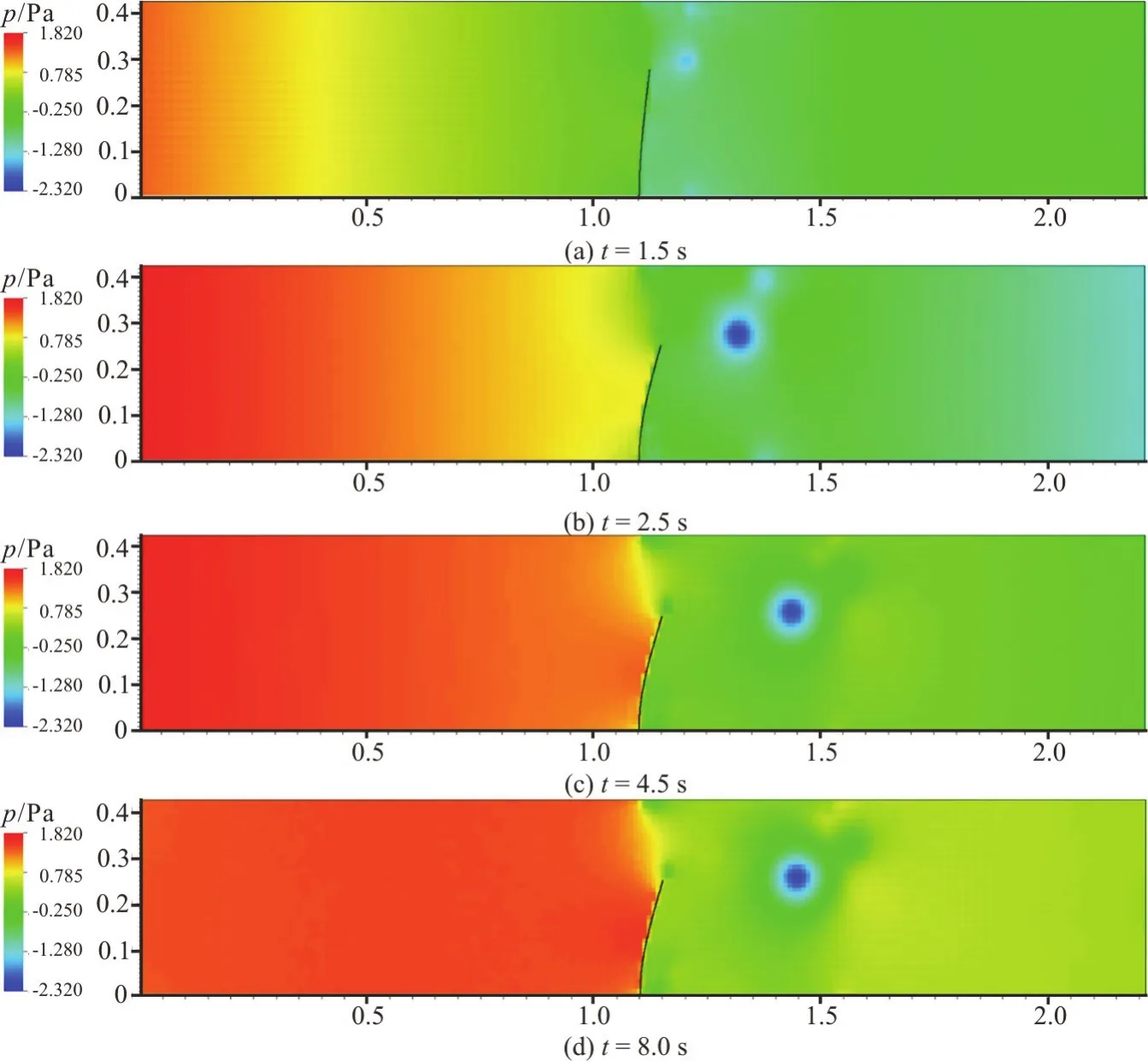
Fig.10 (Color online) Pressure contours of the deformed thin elastic structure obtained using the AMR-IBFEM algorithm at different time steps
4.3 Laminar flow past a moving thin elastic structure
The AMR-IBFEM algorithm is then used to simulate laminar flow past a moving thin structure.The FEM accounts for the deformability of the thin elastic structure,which will improve the accuracy of the predictions in such configurations.Direct numetaking into account the realistic geometry of a membrane valve.The boundary conditions are set as stationary walls with zero velocity for the top and bottom of the computational domain.The boundary condition is set as free flow for the outlet of the domain.The boundary conditions of the inlet are set as follows: (1) flow inlet velocity: 0.3 m/s and (2)flow is fully developed with a symmetric parabolic profile.The Young’s modulus and Poisson ratio of the thin elastic structure are set as 5.0 MPa and 0.3,respectively.The structured mesh consists of 200 nodes.
Figures 9 and 10 show the velocity and pressure contours of the deformed thin elastic structure obtained using the AMR-IBFEM algorithm at different simulation times.It can be seen that the flow velocity is highest (~1.470 m/s) above the structure,beginning from the mid-point of the structure,as indicated by the red region.This region grows as the simulation progresses,however,the flow velocity is reduced.In addition,the flow velocity is reduced to less than 0.1567 m/s within proximity of the thin elastic structure and it is apparent that a region of low flow velocity (marked in dark blue) forms at a distance aft of the structure as the simulation progresses.
It can be seen from Fig.10 that there is a minor difference in the pressure distribution on either side of the thin elastic structure at different time steps.However,there is a large pressure drop as the flow passes by the structure.It shall be noted that this pressure drop refers to the mean pressure difference between the two sides of the structure.The pressure drop across the thin elastic structure increases as the simulation progresses whereas the size of the counter flow region (marked in blue) and the maximum deformation of the valve decreases.Based on the result,it is evident that the AMR-IBFEM algorithm is able to capture the high pressure difference across a structure with ultra-thin thickness.
The mesh size should be sufficiently fine within proximity of the thin elastic structure in order to accurately capture the flow physics at the fluid-solid interface.With the AMR-IBFEM algorithm,the mesh size of the fluid near the boundaries of the thin elastic structure is adapted and refined locally,which eliminates the need to refine the whole computational domain and therefore,this approach is more computationally efficient.The fluid cells and solid nodes are attached to the boundaries without any discontinuity and they are able to capture the arbitrary deformations of the thin elastic structure.The surface integral at the fluid-structure interface is considered massless and can be removed when the stiffness matrix is formed.This treatment eliminates the need to compute the surface forces at the fluid-structure interface.
The computational efficiency of the proposed AMR-IBMFEM algorithm is also assessed in this work in terms of the computational time.The computational time for this test case is found to be 2 203 s(~37 min) for a cell size of Δx=1.25× 1 0-3.In contrast,the computational time is 288 000 s (~80 h)when the is carried out using the IBFEM model with full mesh refinement.This indicates that the computational time for the AMR-IBFEM model is only ~1% of the computational time obtained from full mesh refinement.This test case demonstrates the efficiency of using AMR in computing the fluid flow solutions using IBM.
The drag coefficient (CD) values are determined from the simulation results of the AMR-IBFEM algorithm and the values are compared with those obtained from the ALE algorithm using ANSYS 17.0 software.Here,,whereFxis the total hydrodynamic force in thexdirection.Figure 11 shows the variations of the drag coefficient of the deformed thin elastic structure valve with time obtained from the AMR-IBFEM and ALE algorithms with the same mesh size and initial time step.The error for the drag coefficient is very small(estimated to be ~2%),indicating that there is very good agreement in the drag coefficient values between the AMR-IBFEM and ALE algorithms.However,the AMR-IBFEM algorithm is much simpler in implementation and it is relatively computationally inexpensive.
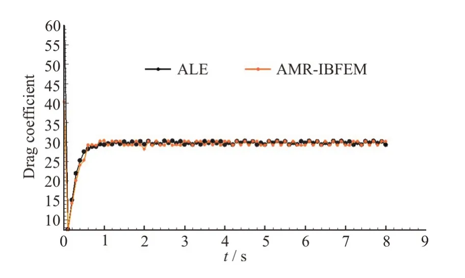
Fig.11 (Color online) Comparison between the drag coefficient values obtained from the AMR-IBFEM and ALE algorithms at Re=20
5.Conclusions
In this work,an improved algorithm was developed to simulate 2-D laminar flows past stationary and moving thin structures.In this algorithm,Kajishima’s cut-cell IBM with two-stage pressurevelocity correction was integrated with FEM and AMR was used to attain high resolution of the flow characteristics within vicinity of the surface of the thin elastic object where large flow gradients are expected.The AMR-IBM algorithm is first verified by comparing the drag coefficient,lift coefficient,and Strouhal number for a benchmark case (laminar flow past a circular cylinder atRe=100 and the results showed good agreement with those of other researchers.The algorithm was then used to simulate laminar flows past stationary and moving thin structures (representative of a membrane valve) in a 2-D domain.The following conclusions were drawn based on the findings of this study:
(1) For the stationary thin structure,the flow velocity is generally higher above the structure,beginning from the mid-point of the structure whereas the flow velocity is significantly lower in the region behind the thin structure.There is a significant pressure drop as the flow passes by the thin structure.
(2) The trends of the velocity and pressure contours for a moving elastic thin structure immersed in laminar flow atRe=20 are similar to those for the stationary thin structure.
(3) There is very good agreement in the drag coefficients obtained from the AMR-IBFEM algorithm and ALE algorithm (error of ~0.02%),which indicates the reliability of the AMR-IBFEM model in simulating 2-D laminar flow past a moving elastic thin structure.
(4) The AMR-IBFEM algorithm eliminates the need to re-mesh the entire computational domain to capture the characteristics of laminar flow past a deformable thin structure such that the computational time is only ~1% of that for simulations with full mesh refinement.Hence,the AMR-IBFEM algorithm is more computationally efficient without compromising the accuracy of the solutions and it is a promising method to simplify the simulations of fluid-structure interaction problems that are typically computationally intensive.
This study can be extended to explore other applications where high mesh resolution is critical such as multi-phase flow problems,3-D problems and high Reynolds.
- 水動力學(xué)研究與進(jìn)展 B輯的其它文章
- Numerical simulation of condensation shock in partial cavitating flow on a hydrofoil*
- Flow regime and energy dissipation of SFS-type flip buckets*
- Spatial and spectral investigation of turbulent kinetic energy in cavitating flow generated by Clark-Y hydrofoil*
- A design of T-foil and trim tab for fast catamaran based on NSGA-II*
- Reconstruction of 3-D surface waves generated by moving submerged sphere based on stereo imaging principle*
- Study of parametric roll in oblique waves using a three-dimensional hybrid panel method*

