Flow regime and energy dissipation of SFS-type flip buckets*
Ran Tian,Jian-hua Wu,Fei Ma
College of Water Conservancy and Hydropower Engineering,Hohai University,Nanjing 210098,China
Abstract: In the present work,a slot-type flip bucket with separated flows,called SFS-type flip bucket,is developed,and flow regime and energy dissipation are experimentally investigated.Comparing with the circular-shaped or slot-type flip bucket buckets,the present SFS-type flip bucket has better flow regime and larger energy dissipation since the three branches of the flows are separated through the outlet of the flip bucket.Meanwhile,the energy dissipation for this flip bucket is estimated.
Key words: Energy dissipation,flow region,separated flow,SFS-type flip bucket
The energy dissipation and flow trajectory of the hydraulic structures are serious concerns[1-3].The circular-shaped flip buckets,as a kind of the element of ski-jump type energy dissipation,are widely used in the release works in hydropower projects[4-5].Due to their simple structure,the suitable hydraulic performance and effective energy dissipation,the circularshaped flip buckets have been reformed,and further developed in order to meet the need of constructions of the projects and to increase energy dissipation,such as the leak-floor[6],the slot-type and multiple slit-type flip buckets[7-8].
The flow is separated into three branches through the leak-floor or slot-type flip bucket,and expanded in the longitudinal or transverse directions.Thus,the energy of the flow is greater dissipated and the scour of the downstream river bed is greater weakened than those through the circular-shaped flip buckets.However,the parts of the flow fall into the leak-floor or the slot from the left and right branches due to the effects of the two side-walls when it leave those type flip buckets,thus affects the flow behavior through the leak-floor or the slot.
The present work developed a kind of the slottype flip bucket with separated flows by means of the two walls of the slot,called SFS-type flip bucket,and three branches of the flow through the flip bucket could be clearly separated.The objectives of this work are to observe the flow regime and to investigate the characteristics of the energy dissipation for the SFS-type flip bucket.
The experiments were conducted in High-Speed Flow Laboratory,Hohai University.The experimental setup consists of a pump,an approach conduit,a large feeding basin,a test model,and a flow return system.Figure 1 is the definition sketch of the energy dissipater geometry and flow regime.The feeding basin issues an approach (subscript o) flow of depthhoand average velocityVo,resulting in the approach flow Froude numberFro=Vo/(gho)0.5.The model discharges are measured with discharge measurement weir instruments.The maximum pump capacityQM= 400 L·s-1,the height differenceS= 0.94 m,and the tailwater channel widthB= 0.70 m.Besides,Hois the water head to the approach channel bottom,h1andh2are the flow depths before and after the hydraulic jump downstream of the jet impact into the tailwater channel,respectively,andV1is the average velocity at the positionh1in order to estimate the energy dissipation of the flip bucket[7].Figures 1(c),1(b) are the plan view and the A-A view of the geometries of the SFS-type flip bucket,respectively,where the approach channel widthBo= 0.15 m,the bucket radiusR=0.50 m,and the deflection angleβ= 35°,bandθare the width and angle of the slot,respectively.Ls=0.70 m andα= 25°,are the horizontal length and angle of the two walls of the slot in the horizontal section,respectively.
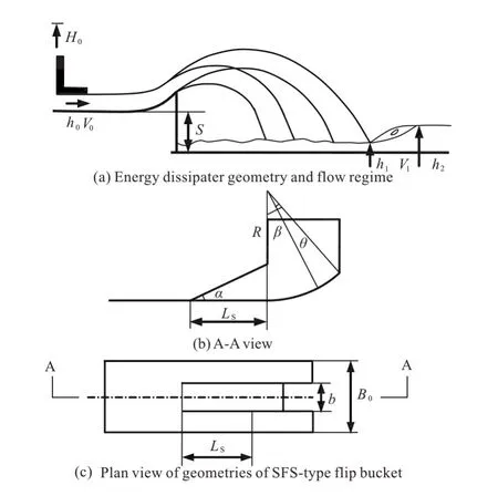
Fig.1 Definition sketch
Table 1 is the cases and parameters of the SFS-type flip bucket models,as well as case M00,the circular-shaped flip bucket withb= 0 m andβ= 35°for the comparison with the SFS-type flip bucket models.The hydraulic characteristics of the SFS-type flip bucket models are investigated through the effects of the parameters ofbandθ,i.e.,M01-M03 and M02-M22.
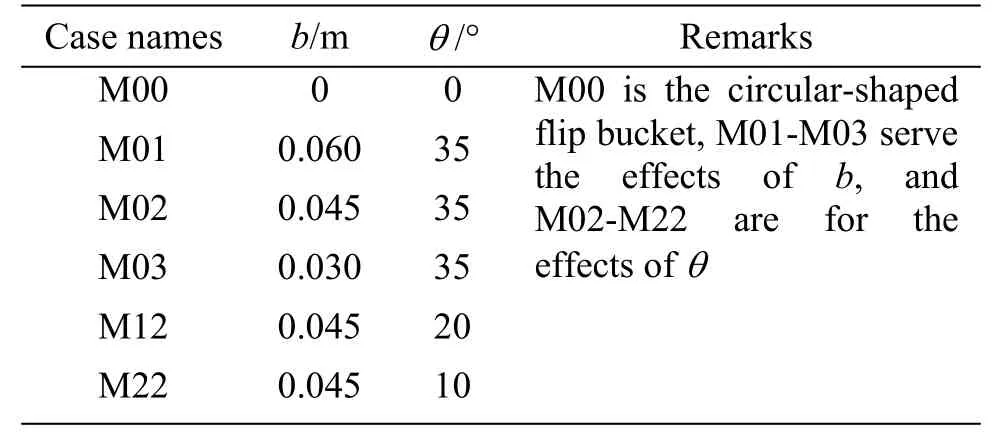
Table 1 Cases and parameters for SFS-type flip bucket models
Figure 2 shows the flow regimes through the different flip buckets at the similar approach flow Froude number,including (a) circular-shaped flip bucket,(b) slot-type flip bucket,and (c) SFS-type flip bucket.
For the circular-shaped flip bucket,there is only a jet flow through it,and its water is relative concentrated (Fig.2(a)).The scope of the impact point is also relative small,thus,this flow produces a serious impact force to the downstream river bed.Besides,the flow choking may occur when the approach flow Froude number is relative small[9-11].
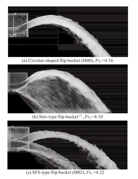
Fig.2 Comparisons of flow regimes with different flip buckets
The slot-type flip bucket forms a sheet flow through the slot in the middle of the flip bucket,and its water is extended in the longitudinal direction along the flow (Fig.2(b)).The scope of the flow entering into the downstream river is greatly increased,then,the energy dissipation is also greatly increased,comparing with the flow through circular-shaped flip bucket[7].The issue to be modified is that the lower trajectory of the flow from the slot is relative small distance to the outlet of the flip bucket due to the flows falling from the two sides into the slot.
The SFS-type flip bucket,proposed in this work,could modify the issue existing in the slot-type flip bucket by means of the two side walls of the slot (Fig.2(c)).It could strictly separate the flow and form three flow branches,and get better energy dissipation through the increasing surface of the air entrainment of the flow and the increasing scope of the flow to the downstream river.
Figure 3 shows the flow regimes through the SFS-type flip buckets at the different approach flow Froude number,Fro= 2.94-4.61.It could be noticed that,the flow trajectory increases with the increase ofFrofor the two side flow branches or the flow through the slot.The flow is clearly separated,and the impact points could be controlled by means of the changes of the deflection angleβand the slot angleθ.
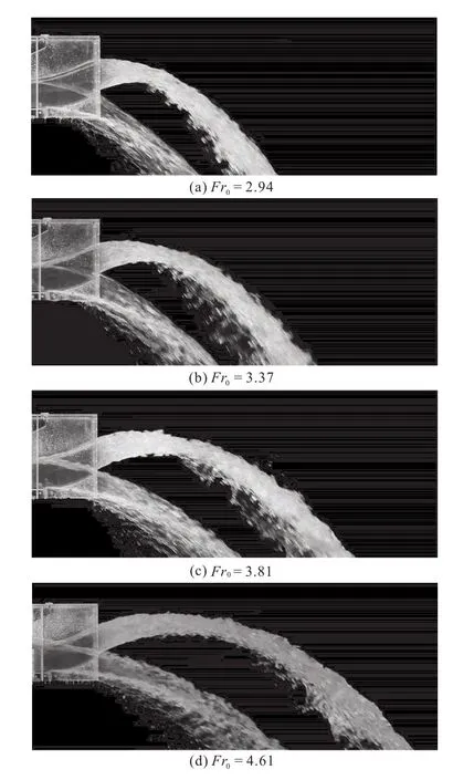
Fig.3 Flow regimes of SFS-type flip bucket at different approach flow (M02)
Figure 4 is the variation ofηwithFroaccording to the experimental results of the different geometric SFS-type flip buckets listed in Table 1,including the result of the circular-shaped flip bucket.In Fig.4,the energy dissipation for all the flip buckets is defined asη= (Ho-H1)/Ho,withHo=ho+S+ (Vo)2/(2g) as the approach flow,andH1=h1+ (V1)2/(2g) as the tailwater energy head.
The energy dissipationηincreases with the increase of the approach flow Froude numberFrofor all the cases listed in Table 1.Obviously,each case of the SFS-type flip buckets has higher energy dissipation than that of the circular-shaped flip bucket thanks to the effects of the slot.The large widthbor the large angleθof the slot could increase the energy dissipation.
Figure 5 shows the variation ofηwith [1 +(b/Bo)0.92?(θ/β)0.84]?Fro0.19for the different geometric SFS-type flip buckets,as well as the circular-shaped flip bucket.The best fit is (R2= 0.916)

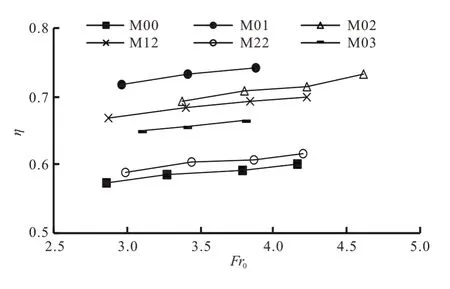
Fig.4 Variation of η with Fro for different flip buckets
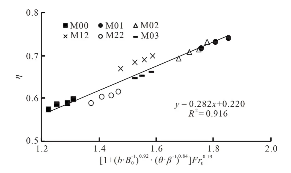
Fig.5 Variation of η with [1 + (b/Bo)0.92?(θ/β)0.84]?Fro0.19
Equation (1) is valid forb/Bo= 0 - 2/5,θ/β=0-1.0,andFro< 4.6.Considering cases M00 and M03 atFro= 4.0,η= 59% and 75%,respectively.It could be clearly seen that,the SFS-type flip buckets has remarkable effect onη.Both largeb/Boand largeθ/βof the flip buckets produce the highηin the ranges of the present study.
In short,a kind of SFS-type flip bucket is proposed in the present work.It could produce better the flow regimes and is of higher energy dissipation comparing with the circular-shaped or slot-type flip buckets.Meanwhile,the estimation of the energy dissipation for this flip bucket is presented.
 水動(dòng)力學(xué)研究與進(jìn)展 B輯2020年1期
- 水動(dòng)力學(xué)研究與進(jìn)展 B輯的其它文章
- Numerical simulation of condensation shock in partial cavitating flow on a hydrofoil*
- Spatial and spectral investigation of turbulent kinetic energy in cavitating flow generated by Clark-Y hydrofoil*
- A design of T-foil and trim tab for fast catamaran based on NSGA-II*
- Adaptive mesh refinement immersed boundary method for simulations of laminar flows past a moving thin elastic structure*
- Reconstruction of 3-D surface waves generated by moving submerged sphere based on stereo imaging principle*
- Study of parametric roll in oblique waves using a three-dimensional hybrid panel method*
