Numerical simulation of condensation shock in partial cavitating flow on a hydrofoil*
Wei Zhang ,Bing Zhu ,Yong Wang,Hui Xu
1.Science and Technology on Water Jet Propulsion Laboratory,Marine Design and Research Institute of China,Shanghai 200011,China
2. School of energy and power engineering,University of Shanghai for Science and Technology,Shanghai 210098,China
3.Max Planck Institute for Dynamics and Self-Organization,G?ttingen 37077,Germany
4. School of Aeronautic and Astronautic,Shanghai Jiao Tong University,Shanghai 200011,China
Abstract: We present a numerical simulation of the so-called condensation shock on a NACA0015 hydrofoil with a finite mass transfer model for the first time.Most recently,condensation shock was indentified in the experimental measurement as a mechanism for partial cavity shedding in the flow past a hydrofoil.Compressible solvers,which were adopted in the previous simulations to study such phenomenon numerically,are extremely time consuming due to the limitation of acoustic Courant number.In this work,we consider a finite mass transfer model for cavitation flow with slightly modification.Our numerical results show that the finite mass transfer model can be successfully applied for calculating the condensation shock in the flow past a hydrofoil.The dynamics of the condensation shock on the hydrofoil is also discussed.The model is proved to be useful for further understanding of the underlying phyiscs of such flow.
Key words: Partial cavitation,condensation shock,finite mass stransfer model
Unsteady partial cavitation in hydrodynamic applications,such as propellers,waterjet pumps such as water turbines,is a crucial phenomenon.It is an important source of the unstable load,noise or even erosive damage for those applications.The underlying physics for the partial cavity shedding had been comprehensively discussed in early literatures[1-3].And in the past decades,re-entrant jet,as shown in Figs.1(a),1(c),is believed to be a major mechanism for the shedding of the cavity[4].A systematical review can be found in the Ref.[5].
Although Jakobsen[6]speculated 20 years ago that an acoustic shock phenomenon could also be the mechanism for unsteady shedding in the partial cavitating flow,it was recently first time confirmed experimentally by Ganesh et al.[7].In that work,bubbly shock propagation in the flow past a convergent-divergent wedge was measured with a time resolved X-ray.And through estimating the Rankine-Hugoniot jump condition locally,the flow measured was believed to be supersonic.Numerically,Budich et al.[8]analyzed the unsteady cavity dynamics,cavitation patterns and instability mechanisms governing partial cavitation for the flow with an in-house compressible solver.Zhanget al.[9]performed simulations for the same case with a compressible RANS solver in OpenFOAM.Both studies reproduced the condensation shock forming at the trailing part of the partial cavity and numerical results are in agreement with the experimental measurement in Ref.[7].
In a most recent work,Wu et al.used the same experiment technique as Ganesh et al.did to study the flow past a NACA0015 hydrofoil[10].They found a multimodal partial cavity shedding phenomenon with a modal of the condensation shock,as shown in Figs.1(b),1(d) and 1(e).
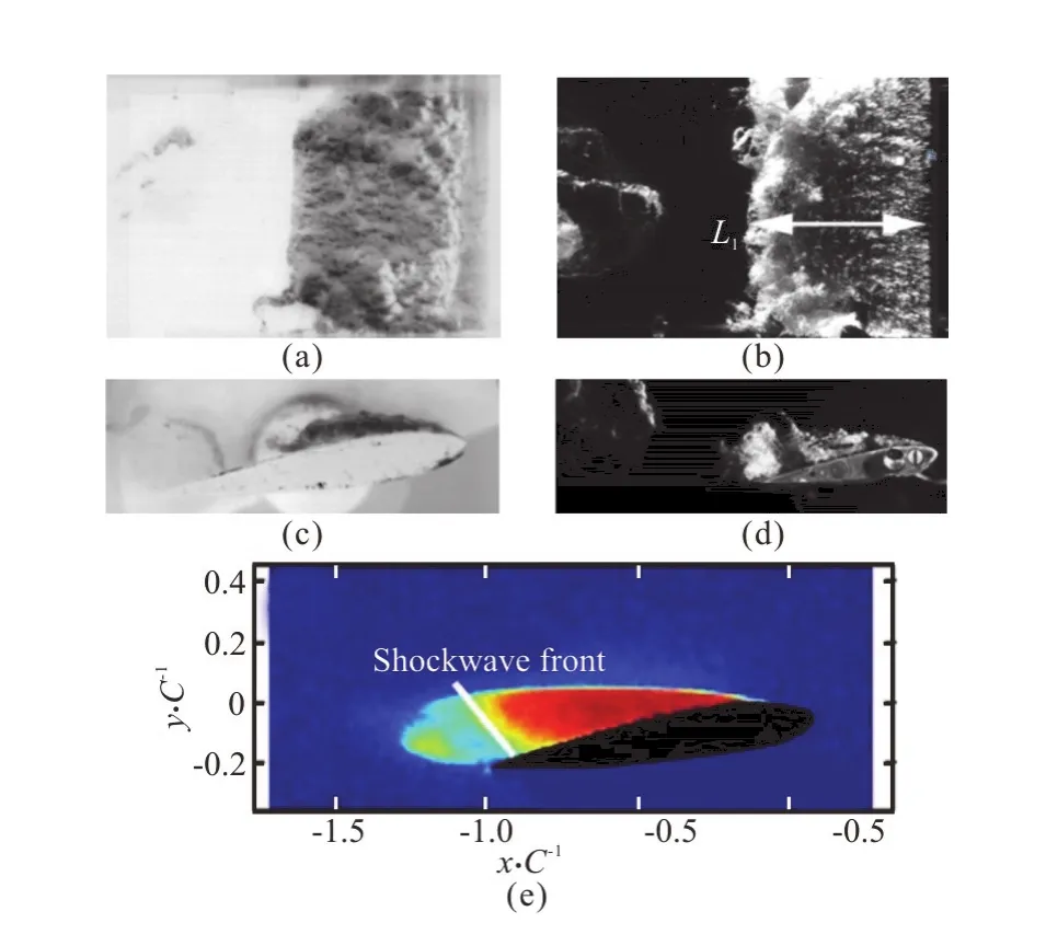
Fig.1 (Color online) Two different modal of partial cavity shedding on a NACA0015 hydrofoil.(a) and (c) are of the re-entrant jet from Ref.[5],(b),(d),(e) are of condensation shock from Ref.[8]
Although the phenomenon is found in the experiment for the flow past a hydrofoil,to the best of our knowledge,there is no published numerical work concerning the condensation shock for the hydrofoil so far.One of the challenges could be that it is very time consuming to run a compressible solver for such flow.With the limitation of acoustic Courant number,the time step size,dt,for a compressible solver is typically in the order ofO(10-8) toO(10-9).While that is normallyO(10-6) for the finite mass transfer model.Considering the existing numerical works,no evidence show the compressibility of the individual phase like water or vapor plays as a key role in the condensation shock,though the flow is thought to be supersonic.On the contrary,the phenomenon involves collapse,in which the water vapor condenses to the liquid.Condensation shocks form as the collapse propagate to the upstream.Schenke and Terwisga[11]have proved that a finite mass transfer model of cavitation for the incompressible solver can reproduce theρ-ptrajectory similar to the equation of state for phase transient.This indicates that a finite mass transfer model could be used to capture the condensation shock.
Inspired by the previous studies,we use the build-in incompressible cavitation solver,interphase-ChangeFoam,in OpenFOAM with a modified Merkle model[12].It reads as:


whereu,pare the mixture velocity and pressure respectively,γis the volume fraction of the liquid.The model parametersCcandCvare specified as 5 000 kg?s?m5and 2 500 kg?s?m5respectively based on the validation in Ref.[13].Viscosities for both water and vapor are set to be zero as the convection is a dominating factor.NACA0015 foil is considered in this study as corresponding experimental measurement is avaliable in the literature for comparison.The angle of attack used in the simulation is 8°,same as that in the measurement work of Ref.[8].The computational domain is 0.56 m×0.04 m×0.08 m.Both side wall boundaries are set to be symmetry.A constant velocityUrefis specified at the inlet plane,while constant pressurePrefis given at the outlet boundary.The cavitation number,,is set to be 2.05 and 1.00,where the vapor pressurePsatis 1 875 Pa.The mesh is refined locally around the hydrofoil,as shown in Fig.2.Total number of cells is 1 336 824 and the length scale of the finest cell is 0.3125 mm.Mesh refinement studies in Ref.[13]show that such resolution is reasonable.
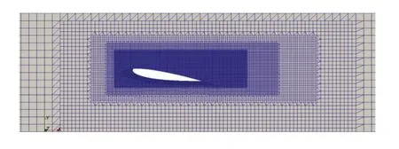
Fig.2 (Color online) Local mesh around the foil
First of all,a numerical result for caseσ=2.05 is given in Fig.3.The cavitation pattern is shown with the isosurface withαwater=0.5,whereαwateris volume fraction of the water.A typical pattern of re-entrant jet modal with a horse shoe cavitation structure is captured,similar to the data with high-speed videography shown in Figs.1 (a),1(c).
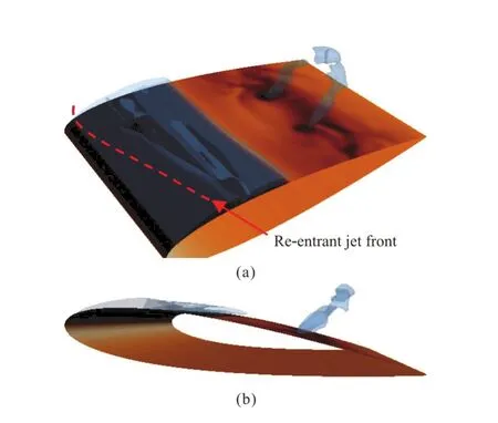
Fig.3 (Color online) A typical re-entrant jet modal for flow past a Naca0015 hydrofoil of σ=2.05
A typeical sheding period for caseσ= 1.00 is given in Fig.4.From the isosurfaceαwater=0.5of six different time instants within one period,it can be seen that the vapor cavity forms at near the leading edge of the air foil in the suction side (Fig.4(a)).It grows to the maxima as shown in Fig.4(b).At this moment a large sheet vapor cavity fully covers the pressure side of the foil,similar to the super-cavitation.At the closure of sheet cavity,there is a turbulent frothy cavitation structure.This can also be seen from the high-speed videography in Fig.1(b).The collapse starts then from the frothy wake as shown in Fig.4(c).
The shock front as indicated by a red dash line in this figure forms between the closure of cavity and the bubbly wake.From the side view of Fig.4(c).Similar pattern can be found in the x-ray measurement (Fig.1(e)) in Ref.[8].The bubbly shock then propagates upstream as shown in Figs.4(d),4(e).During the propagation the shock front is three-dimensional.It evolves with the mixture structure.This indicates there is strong interaction between the bubbly shock and turbulent flow.Once the shock front reaches the leading edge,a large cloud cavitation is pinched off(Fig.4(f)).
The contour ofαwaterat mid-plane of these six time instants are given in Fig.5.It can be seen clearly in Fig.5(a) that cavitation grows from the leading edge.At the very early stage of the collapse,as shown in Figs.5(b),5(c),the shock front is difficult to identify in the mid-plane.In fact,it is also difficult to identify the shock front in planes parallel to the mid-plane during the early stage of shedding.This differs from the x-ray measurement since the latter is an integral measurement for void fration.The measured void fraction is the averaged over the spanwise direction.Still an inhomogeneous cavitation structures can be found in the wake of sheet cavitation.Once the collapse of the cavitation structure moves upward,a sharp interface can be found between the sheet cavitation and bubbly mixture in the mid-plane as shown in Fig.5(d).This is similar to the simulation for the cavitating flow past a wedge,where a compressible solver was adopted[9].
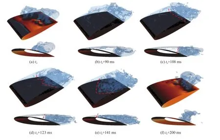
Fig.4 (Color online) Time series of instantaneous contour of αw at er for σ=1.00 and U =17.8 m/sin one period.The red dash lines indicate the location of shock front.Both top view and side view are given
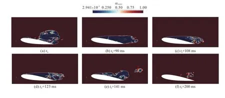
Fig.5 (Color online) Time series of instantaneous contour of αw at er for σ = 1.00 and U =17.8 m/s in one period at the mid-plane
Furthermore,a probe was set in the middle plan close to the leading edge as in the Ref.[13].The power spectrum of the pressure fluctuation forσ=2.05,1.00 are shown respectively in Fig.6.The characteristic frequency of 192 Hz is in good agreement to the measured work 188 Hz in Ref.[5].For caseσ= 1.00,two characteristic frequencies,35 Hz,65 Hz,are found like in the Ref.[10].Similarly,these frequencies are much smaller than that of caseσ= 2.05,where the re-entrant jet is the dominant phenomenon.
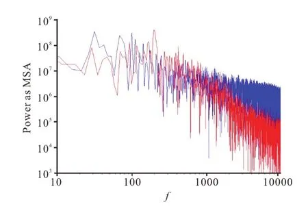
Fig.6 (Color online) The power spectrum of pressure fluctuation for σ=2.05 (red),1.00 (blue) for and U=17.8 m/s
In summary,we show a numerical simulation for the flow past a hydrofoil in the present work.The so-called condensation shock is captured with a finite mass transfer model for the cavitation based on an incompressible solver in OpenFOAM.The Merkle model is modified to reproduce solutions similar to the equation of state computationally,as the latter is much more computational expensive for such case.The results of dynamics of cavitation structure agree well with those from the x-ray and high-speed videography measurements,for not only re-entrant jet caused partial cavity shedding but also the condensation shock.The progress of the shock front,in three-dimensional,are clearly observed in the simulation.This work demonstrates that the incompressible solver can also be used to calculate the condensation shock in the partial cavity shedding in the leading edge of a hydrofoil.The method we adopted here can be used to study the flow feature of the condensation shock.Further study should be taken carefully for the interaction between condensation shock and the turbulent frothy wake near the closure of the sheet cavity.
- 水動力學(xué)研究與進(jìn)展 B輯的其它文章
- Flow regime and energy dissipation of SFS-type flip buckets*
- Spatial and spectral investigation of turbulent kinetic energy in cavitating flow generated by Clark-Y hydrofoil*
- A design of T-foil and trim tab for fast catamaran based on NSGA-II*
- Adaptive mesh refinement immersed boundary method for simulations of laminar flows past a moving thin elastic structure*
- Reconstruction of 3-D surface waves generated by moving submerged sphere based on stereo imaging principle*
- Study of parametric roll in oblique waves using a three-dimensional hybrid panel method*

